Forming mold and forming method for composite material tubular parts with flanges

A technology of composite materials and tubular parts, applied in household components, household appliances, other household appliances, etc., can solve the problems of prepreg laying difficulties and other problems, achieve simple and fast laying, reduce scrap rate, and high-quality product appearance. Effect

Inactive Publication Date: 2018-08-17
JIANGSU MEILONG AVIATION COMPONENTS
View PDF5 Cites 10 Cited by
  • Summary
  • Abstract
  • Description
  • Claims
  • Application Information

AI Technical Summary

Problems solved by technology

[0003] Purpose of the invention: In view of the above-mentioned problems, the purpose of the present invention is to provide a molding die with a flange-like composite material tubular part, and a forming method for using the mold to process a flange-like composite material tubular part, so as to solve the problem of having a flange-like composite material. Difficulty in laying prepreg materials during the processing and molding of tubular parts, so as to realize the smooth demoulding of products after molding, so that composite tubular parts with flanges can be integrally formed

Method used


Image

  • Forming mold and forming method for composite material tubular parts with flanges
  • Forming mold and forming method for composite material tubular parts with flanges
  • Forming mold and forming method for composite material tubular parts with flanges

Examples


Embodiment Construction

[0032] The present invention will be further illustrated below in conjunction with the accompanying drawings and specific embodiments, and it should be understood that these embodiments are only for illustrating the present invention and are not intended to limit the scope of the present invention.

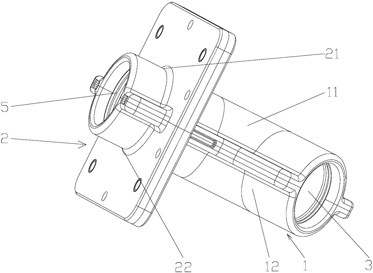
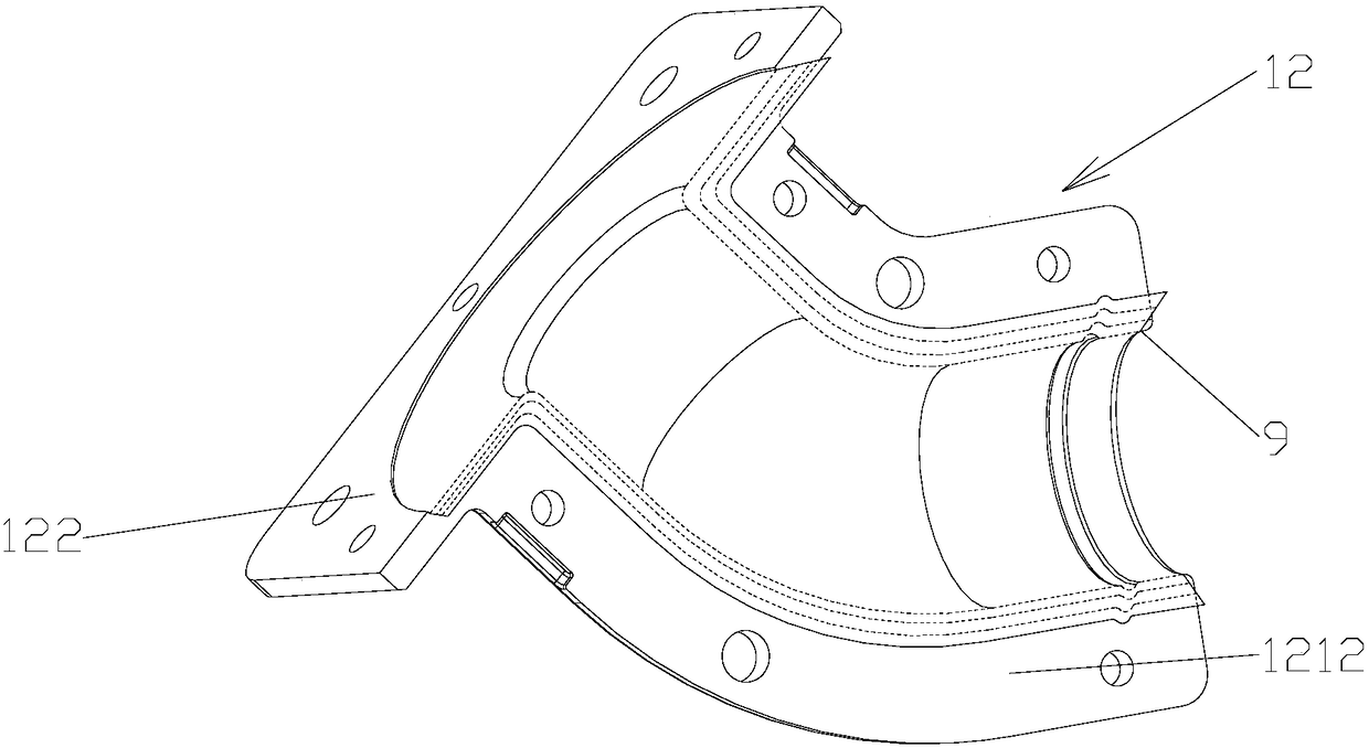
[0033] A forming die for tubular parts of composite material with flanges, such as Figure 1-8 As shown, it includes a combined mold one 1 formed by the docking of split mold one 11 and split mold two 12, and a combined mold two 2 formed by butt jointing of split mold three 21 and split mold four 22, and combined mold one 1 and combined mold two 2 close the mould.

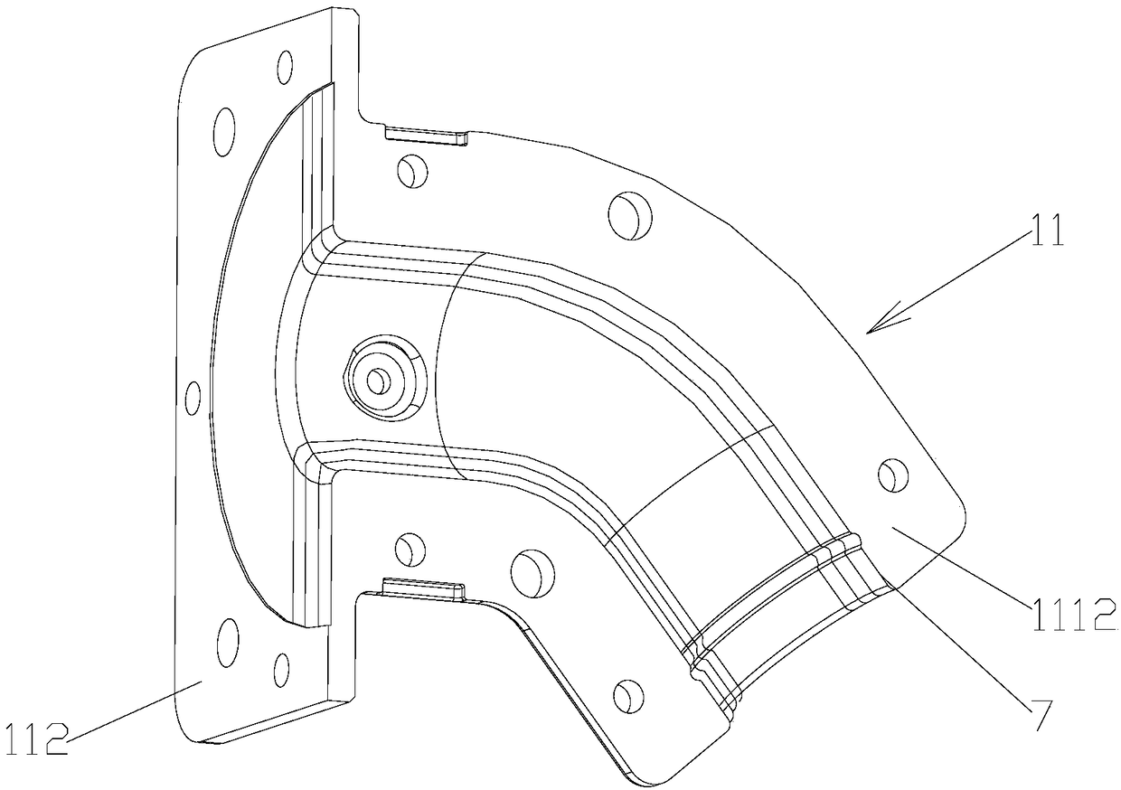
[0034] Split mold one 11 comprises integrally formed half-type pipe one 111, half-type flange one 112, and half-type flange one 112 is connected with an end of half-type pipe one 111, and half-type pipe one 111 includes pipe body one 1111, two Flange 1 1112, flange 1 1112 is integrally formed and connected with pipe b...


PUM


Abstract

The invention discloses a forming mold for composite material tubular parts with flanges. The forming mold for the composite material tubular parts with the flanges comprises a first combined mold anda second combined mold; the first combined mold is provided with a first pipe cavity and a first annular cavity; the first pipe cavity and the first annular cavity communicate with each other at theposition of a pipe port in one end of the first pipe cavity; the second combined mold is provided with a second pipe cavity and a second annular cavity; the second pipe cavity and the second annular cavity communicate with each other at the position of a pipe port in one end of the second pipe cavity; the first combined mold and the second combined mold are subjected to mold closing, and the firstannular cavity is made to communicate with the second annular cavity; and a forming method for using the forming mold to machine the composite material tubular parts with the flanges is disclosed. The forming mold has the beneficial effects that by performing combined design on the forming mold, in the forming process of the composite material tubular parts with the flanges, paving and pasting ofprepreg can be easier and faster, and operation is convenient; after curing molding of the tubular parts, demolding of the forming mold can be achieved easily, and operation is easy and convenient; and the production efficiency is improved, and practicability is high.

Description

technical field [0001] The invention relates to a molding die and a molding method of a composite material part, in particular to a molding mold and a molding method of a composite material tubular part with a flange. Background technique [0002] In the molding of composite materials, the existing overall mold forming method cannot realize the molding of composite tubular parts with flanges, and the overall mold forming method cannot realize the prepreg laying of composite tubular parts with flanges, making the molding The process is very difficult. Even if the paving is completed, it is very difficult to demould the molded product. It is difficult to demould after molding regardless of whether the integral mold of the female mold or the integral mold of the male mold is used. In addition, the integral mold forming method is also difficult. It is difficult to realize integral molding of the flange part and the tubular part. Contents of the invention [0003] Purpose of t...

Claims


Application Information

Patent Timeline
Patent Type & Authority Applications(China)
IPC IPC(8): B29C70/30B29C33/48B29L31/24
Inventor 柳毅朱桂龙张毅
Owner JIANGSU MEILONG AVIATION COMPONENTS
Why Eureka
Try Eureka