Valve box, tank container and box door mounting structure

A valve box and box door technology, which is applied in the field of valve boxes, can solve the problems of increasing the number of welds in the tank, theft of the transport medium, and the increased risk of tank failure, so as to improve the anti-prying ability, prevent damage, and ensure the structure The effect of intensity

Pending Publication Date: 2018-08-17
CRRC YANGTZE CO LTD
View PDF0 Cites 1 Cited by
  • Summary
  • Abstract
  • Description
  • Claims
  • Application Information

AI Technical Summary

Problems solved by technology

Welding support pads on the tank to install the valve box, or directly welding the valve box to the tank will increase the number of tank welds and increase the risk of tank failure
[0004] In addition, the door of the valv

Method used


Image

  • Valve box, tank container and box door mounting structure
  • Valve box, tank container and box door mounting structure
  • Valve box, tank container and box door mounting structure

Examples


Embodiment 1

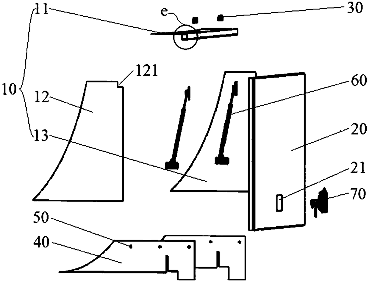
[0057] see figure 1 , a valve box, including a box body 10, a box door 20 and a support device 40, the support device 40 is located below the box body 10, and the box body 10 is installed on the support device 40.

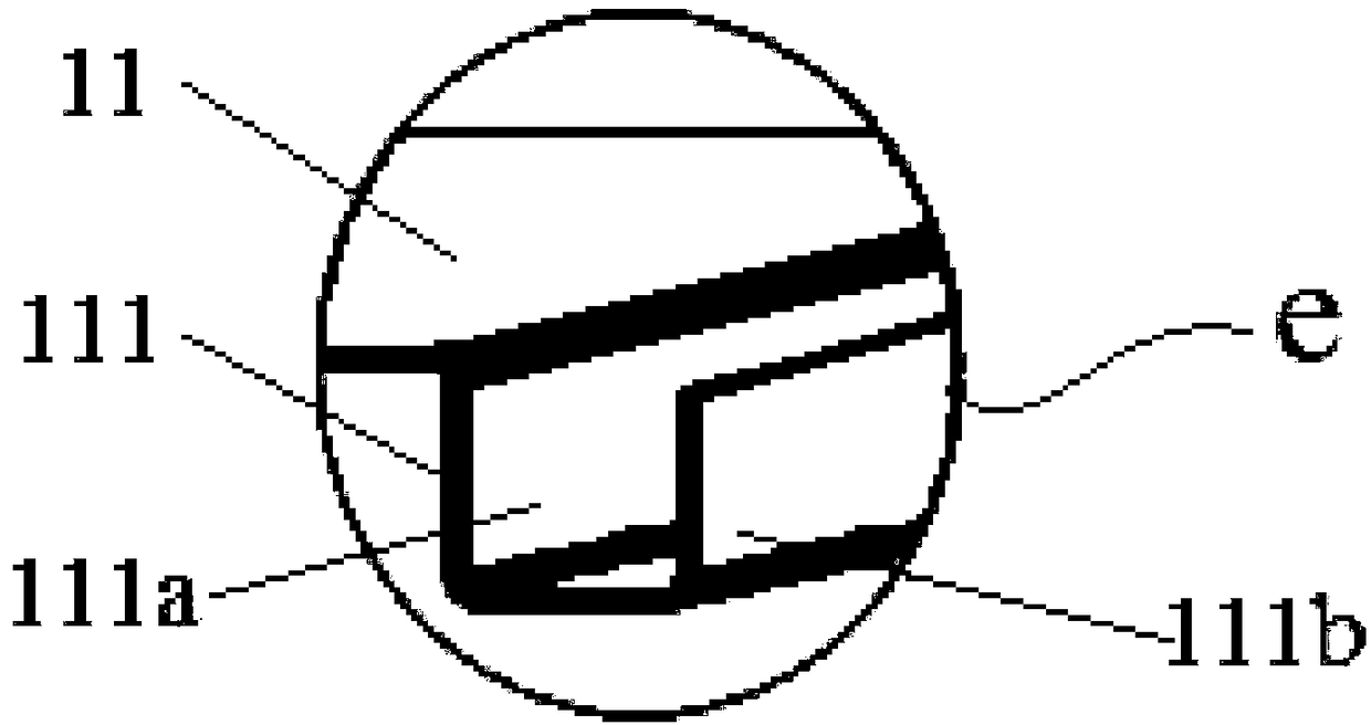
[0058] The box body 10 includes a top board 11 , a left side board 12 and a right side board 13 , and the box door 20 is hinged to the top board 11 through a hinge member 30 . The inner side of the box door 20 and the position of the top plate 11 for installing the box door 20 are all provided with hinged positions; the two hinged positions are opposite to each other, and jointly define a sinking hinged area, the height of which is not higher than the top plate 11 The upper surface; the hinged part 30 is installed in the hinged area, between the door 20 and the top plate 11, and the hinged part 30 is respectively connected with two hinged positions.

[0059] In the embodiment of the present invention, the box body 10 has no bottom plate, and is composed of a top p...

Embodiment 2

[0068] see Figure 5 , a valve box, comprising a box body 10 and a box door 20, the box body 10 includes a top plate 11, a left side plate 12 and a right side plate 13; the box door 20 is hinged with the top plate 11 through a hinge part 30, and the length of the top plate 11 is in the box The door installation side is slightly shortened, avoiding the space for the installation of the hinged parts 30; the length of the left side panel 12 and the right side panel 13 is lengthened, and its bottom just rests on the frame of the tank container after installation.

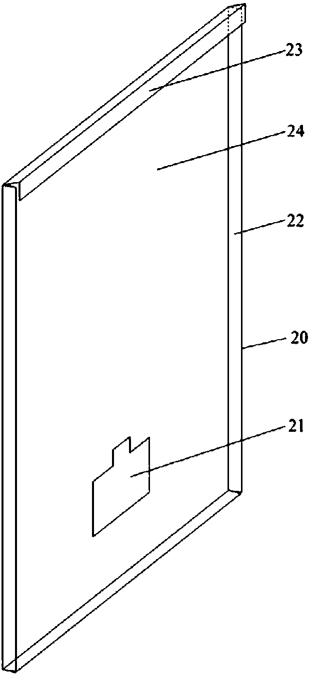
[0069] see Figure 6 , the inside surface of the box door 20 and the position of the top plate 11 for installing the box door 20 are provided with hinged positions 91, 92, wherein the box door hinged positions 91 are two pieces welded on the inner surface of the box door 20 and distributed at intervals The top plate hinged position 92 is two plates welded on the lower surface of the top plate 11 and distributed at inte...


PUM


Abstract

The invention discloses a valve box, a tank container and a box door mounting structure. The valve box is mounted on the frame of the tank container and comprises a box body and a box door, wherein the box body comprises a top plate, a left side plate and a right side plate; the box door is hinged to the top plate through a hinge joint component; hinge joint positions are arranged on the inner side face of the box door and the part, for mounting the box door, of the top plate; the two hinge joint positions are opposite and jointly define a sinking hinge joint area; the height of the hinge joint area is not larger than the upper surface of the top plate; and the hinge joint component is mounted in the hinge joint area, is positioned between the box door and the top plate and is connected with the two hinge joint positions. According to the invention, the mounting structure of the valve box is improved, and the valve box is mounted on the frame to enable the entire valve box and a tank body not to have any connecting relation, so that welding with the tank body is avoided and the structural strength of the tank body is ensured. The box door of the valve box is mounted by adopting theembedded hinge joint component and is difficult to dismantle, so that a transportation medium is prevented from being stolen.

Description

technical field [0001] The application belongs to the technical field of tank containers, and in particular relates to a tank container and its associated valve box. Background technique [0002] Tank container, referred to as tank container, is a widely used storage and transportation equipment. The device is composed of centralized installation in the valve box. The valve box is an important accessory device on the tank container, which has the functions of protecting the loading and unloading system, preventing accidental opening and anti-theft. [0003] Most of the valve boxes used in the existing tank products on the market are welded one-piece structures. The valve boxes are directly welded to the tank body or installed on the support pads drawn from the tank body, and the support pads are welded to the tank body. The tank is an important part of the tank, which bears the gravity and inertial load of the medium in the tank and transmits the load. In the liquefied gas...

Claims


Application Information

Patent Timeline
IPC IPC(8): B65D90/02B65D90/54
CPCB65D90/02B65D90/54
Inventor 黄政贤霍海波熊珍艳胡海滨何远新吕长乐
Owner CRRC YANGTZE CO LTD
Why Eureka
Try Eureka