
Automatic chain tensioning mechanism

A tensioning mechanism and chain technology, applied in the direction of conveyors, transportation and packaging, etc., can solve the problems of large space occupation and high maintenance intensity, and achieve the effect of reasonable structure and enhanced anti-rotation effect

Pending Publication Date: 2018-08-17
安歌科技(集团)股份有限公司
View PDF0 Cites 0 Cited by
  • Summary
  • Abstract
  • Description
  • Claims
  • Application Information

AI Technical Summary

Problems solved by technology

[0004] The purpose of the present invention is to overcome the shortcomings of the above-mentioned prior art and provide an automatic chain tensioning mechanism, which aims to solve the technical problems that the chain tensioning mechanisms commonly used in the prior art are either high in maintenance strength or occupy a large space

Method used


Image

  • Automatic chain tensioning mechanism
  • Automatic chain tensioning mechanism

Examples


Embodiment Construction

[0018] In order to make the object, technical solution and advantages of the present invention clearer, the present invention will be further described in detail below with reference to the accompanying drawings and embodiments. However, it should be understood that the specific embodiments described here are only used to explain the present invention, and are not intended to limit the scope of the present invention. Also, in the following description, descriptions of well-known structures and techniques are omitted to avoid unnecessarily obscuring the concept of the present invention.

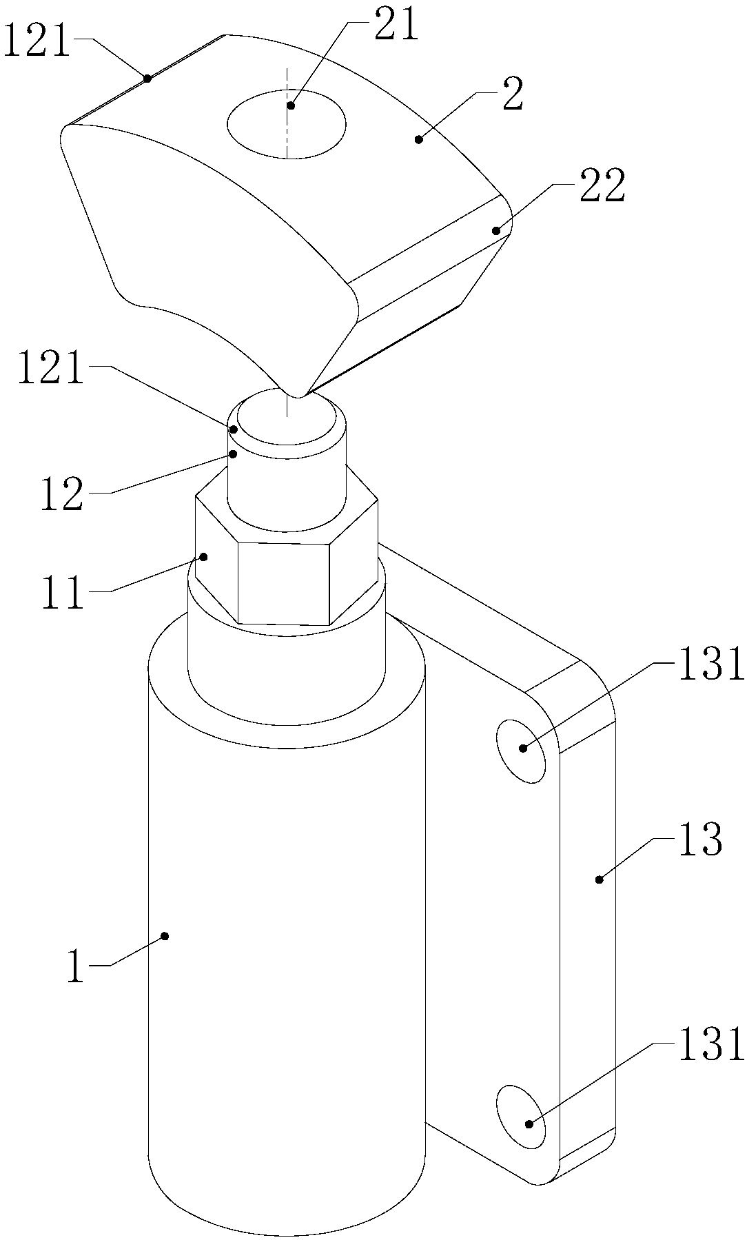
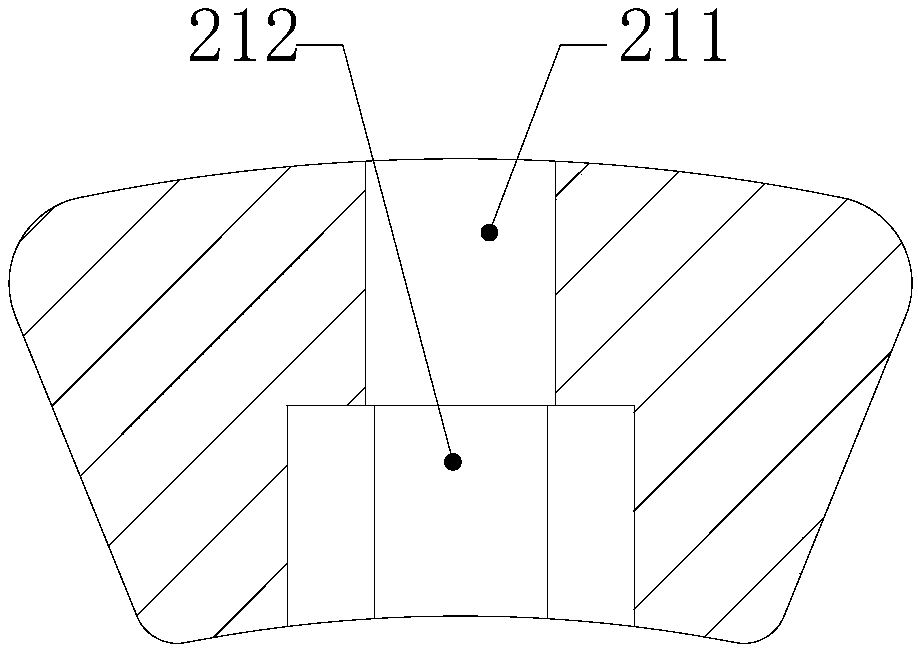
[0019] refer to figure 1 and figure 2 The embodiment of the present invention provides an automatic chain tensioning mechanism, which includes a cylinder 1 filled with inert gas and a top block 2 , the head of the piston rod of the cylinder 1 is mated with the positioning hole 21 provided on the top block 2 .

[0020] Further, the piston rod head of the cylinder 1 is composed of a hexagonal...


PUM


Abstract

The invention discloses an automatic chain tensioning mechanism. The automatic chain tensioning mechanism comprises an air cylinder inflated with inert gas and an ejector block. The head of a piston rod of the air cylinder is connected with a positioning hole in a matched manner, and the positioning hole is formed in the ejector block. The provided automatic chain tensioning mechanism is reasonable in structure, the head of the piston rod of the air cylinder is composed of a hexagonal shaft and a cylinder head, the hexagonal shaft and the cylinder head are matched with an inner hexagonal holeand a circular hole in the ejector block correspondingly so that after the ejector block and the head of the piston rod of the air cylinder are matched, the position can be determined, and rotation cannot happen. In addition, through cooperation of an upper convex arc face at the lower end of the ejector block and an upper convex arc face on the piston rod of the air cylinder, the rotation preventing effect can be further enhanced. In the chain tensioning process, the inert gas with which the air cylinder is inflated can make the interior of the air cylinder constantly kept at a certain pressure, a chain is in a tensioned state, and the problems that a bolt ejector rod manner is adopted at present, and regular maintenance and adjustment are needed; and a balance weight block increasing manner is adopted, and the occupied space is large are solved.

Description

【Technical field】 [0001] The invention relates to the technical field of chain drive tensioning, in particular to an automatic chain tensioning mechanism. 【Background technique】 [0002] The main transmission mode of the conveyor table equipment used in the intelligent three-dimensional warehouse is chain transmission. Since the chain drive must use the chain tensioning mechanism, the quality of the chain tensioning mechanism is more important for the use and maintenance of the conveyor table. Now commonly used chain tensioning mechanism, a kind of is the mode that uses bolt push rod, another kind of mode that relies on counterweight to pull down. Due to various reasons such as mechanical vibration during use, the bolt ejector method often moves its position and loosens, requiring maintenance workers to check and adjust on a regular basis, perform maintenance, and re-tension; It can ensure that the chain is always in tension, but it needs to increase the counterweight, whi...

Claims


Application Information

Patent Timeline
IPC IPC(8): B65G23/44
CPCB65G23/44
Inventor 张晓东姜跃君
Owner 安歌科技(集团)股份有限公司
Learn More