Check patentability & draft patents in minutes with Patsnap Eureka AI!

A fixture for tubular parts

A technology of parts and fixtures, which is applied in the field of clamping devices, can solve problems such as axial movement of tubular parts, achieve the effects of reducing gaps, increasing friction, and preventing axial sliding

Active Publication Date: 2019-05-17
宁波辉励铭诚汽车零部件有限公司
View PDF5 Cites 0 Cited by
  • Summary
  • Abstract
  • Description
  • Claims
  • Application Information

AI Technical Summary

Problems solved by technology

[0004] The present invention intends to provide a clamp for tubular parts to overcome the problem of axial movement of tubular parts in the prior art during clamping and lifting

Method used


Image

  • A fixture for tubular parts
  • A fixture for tubular parts
  • A fixture for tubular parts

Examples


Embodiment Construction

[0019] The present invention will be described in further detail below by means of specific embodiments:

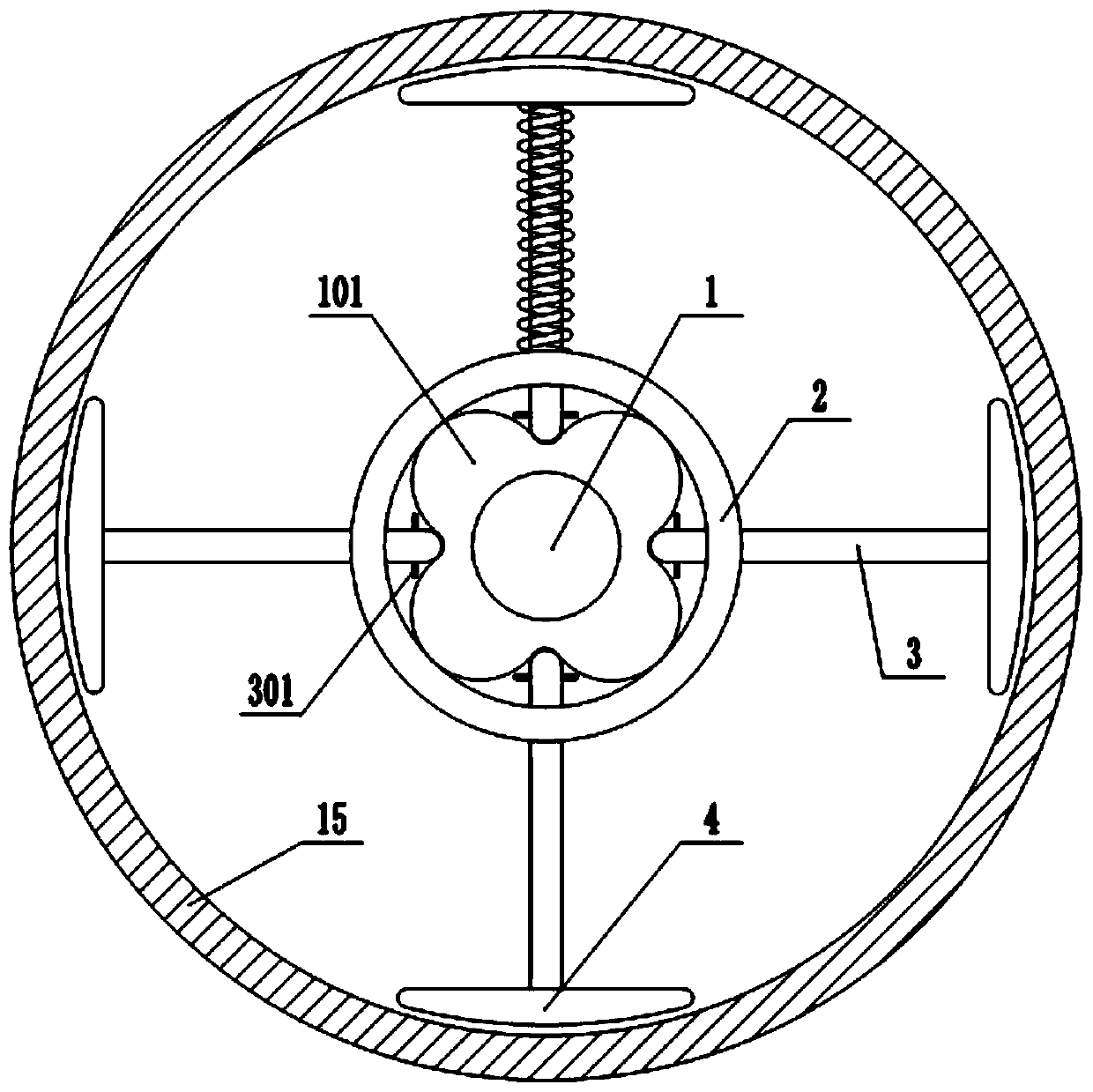
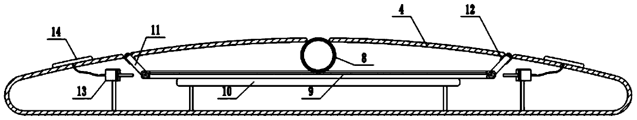
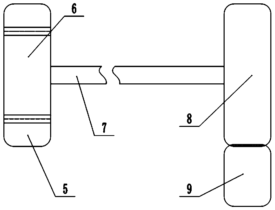
[0020] The reference signs in the drawings of the description include: the first rotating shaft 1, the arc-shaped convex part 101, the limit ring 2, the support rod 3, the limit plate 301, the support plate 4, the internal gear 5, the first external gear 6, The second rotating shaft 7, the second external gear 8, the rack 9, the support frame 10, the slide bar 11, the limit tube 12, the cylinder 13, the elastic air bag 14, and the tubular parts 15.

[0021] The embodiment is basically as attached Figure 1 to Figure 3 Shown: a fixture for tubular parts, including a first rotating shaft 1, a limit ring 2, a support rod 3, the first rotating shaft 1 is connected with a driving motor, and the first rotating shaft 1 is rotatably connected with lifting lugs; the first Rotating shaft 1 is provided with several arc-shaped protrusions 101 along the circumferential surface, the c...


PUM


Abstract

The invention relates to the technical field of hoisting clamps, and discloses a clamp for tubular parts. The clamp for the tubular parts comprises a first rotation shaft, a limiting circular ring, and a support rod. The first rotation shaft is provided with an arc convex part. The support rod slidably passes through the side wall of the limiting circular ring. One end of the support rod is slidably connected with the surface of the arc convex part. One end of the support rod is fixedly connected with a support plate. The outer surface of the support plate is provided with a first opening. Aninternal gear is rotatably connected in the support plate. The outer surface of the internal gear contacts with the first opening. The internal gear is internally meshed with a first external gear. The first external gear is coaxially connected with a second external gear. The second external gear is meshed with a rack. Two ends of the rack are hinged with a slide bar. Along with the axial movement of the tubular part, the internal gear drives the slide bar to be moved, a friction force between the inner wall of the tubular part and the clamp is increased, and the tubular part is prevented from being continuously moved. The clamp is capable of clamping and hoisting the tubular parts, and has the advantage of controlling the axial movement of the tubular parts in time.

Description

technical field [0001] The invention relates to the technical field of hoisting fixtures, in particular to a clamping device. Background technique [0002] In the process of processing tubular parts, it is usually necessary to use clamps to fix them before they can be lifted. However, in the prior art, the clamping and fixing of clamps and tubular parts is not reliable, and the tubular parts may still occur along the axis. Moving, even the danger of falling will occur in serious cases, and it will also affect the accuracy of the positioning of tubular parts, which is not conducive to production. [0003] Therefore, how to improve the problem of axial movement of tubular parts during clamping and lifting is an urgent problem to be solved now. Contents of the invention [0004] The present invention intends to provide a clamp for tubular parts to overcome the problem of axial movement of the tubular parts in the prior art during clamping and lifting. [0005] In order to a...

Claims


Application Information

Patent Timeline
Patent Type & Authority Patents(China)
IPC IPC(8): B66C1/46
CPCB66C1/445B66C1/46B66C1/56
Inventor 王作栋
Owner 宁波辉励铭诚汽车零部件有限公司
Features
  • R&D
  • Intellectual Property
  • Life Sciences
  • Materials
  • Tech Scout
  • Unparalleled Data Quality
  • Higher Quality Content
  • 60% Fewer Hallucinations
Learn More