
Cooling device for fiber production

A cooling device and fiber technology, applied in the field of elastic fiber production, can solve problems such as poor operating rate, reduced fiber draft performance, and influence on spinning effect

Pending Publication Date: 2018-08-17
湖州虹君机械有限公司
View PDF4 Cites 2 Cited by
  • Summary
  • Abstract
  • Description
  • Claims
  • Application Information

AI Technical Summary

Problems solved by technology

However, when preparing some unstable monofilaments, such as polyester amide, due to the unstable characteristics of its molecular chain, a small amount of small molecules will be produced during the spinning process. These small molecules will not only reduce the fiber traction Extensibility, and at the same time, it will escape into the air and affect the production environment
For example, if the outer ring blowing method is adopted, due to the high wind speed (0.8 to 8.0m / s), it is easy to disturb the spinning and affect the spinning effect; these unstable monofilament bundles are directly blown by the high wind speed The tow is cooled immediately, the pre-orientation degree of the tow is high, and the drawing performance of the fiber is poor
In the production process, the operating rate is poor, the output of waste silk is high, and the product quality cannot meet the needs of users

Method used


Image

  • Cooling device for fiber production

Examples


Embodiment Construction

[0013] The present invention is not limited by the following examples, and specific implementation methods can be determined according to the technical solutions of the present invention and actual conditions.

[0014] Below in conjunction with embodiment and accompanying drawing, the present invention will be further described:

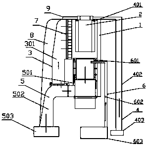
[0015] Such as figure 1 As shown, the cooling device for fiber production, the cooling device for fiber production, includes a housing 1 with an accommodation space, a spinning channel 2, an air inlet device 3, an internal suction device 4, and an external suction device 5 , the surrounding air blowing device 6 and the stabilizing tube 7 that is open at both ends; the accommodating space is surrounded by the air intake cover 8, the housing 1 and the top cover 9, and the internal suction device 4 includes an annular internal suction that is connected in sequence The air duct 401, the inner suction duct 402 and the inner suction pump 403; the outer su...


PUM

PropertyMeasurementUnit
heightaaaaaaaaaa

Abstract

The invention relates to the technical field of elastic fiber production, in particular to a cooling device for fiber production. The cooling device comprises a shell with a containing space, a spinning channel, an air inlet device, an inner air suction device, an outer air suction device, a circular air blowing device, and a flow stabilization cylinder with both ends open; the containing space isdefined by an air inlet hood, a shell and a top cover, and the inner air suction device comprises an annular inner air suction pipe, an inner air suction pipe and an inner air suction pump which areconnected in sequence; the outer air suction device comprises an annular outer air suction pipe, an outer air suction pipe and an outer air suction pump which are connected in sequence; the annular inner air suction pipe sleeves the upper portion of the spinning channel, and the annular outer air suction pipe sleeves the annular inner air suction pipe. By combining air suction and air blowing, small molecules and other harmful gases generated in the spinning process can be sucked away to reduce harm to the environment, and the disturbance of the air blowing device to the spinning process can be reduced to meet user requirements; the cooling device is especially suitable for unstable spinning cooling.

Description

technical field [0001] The invention relates to the technical field of elastic fiber production, in particular to a cooling device for fiber production. Background technique [0002] In the fiber production process, synthetic fibers are extruded from a polymer melt through a spinning nozzle with multiple spinneret holes during melt spinning. These filaments must be cooled in order to be accepted as tow after further processing. In the existing spinning device, air is usually used as the cooling medium, and the air flows transversely to the running direction of the filament and aligns the monofilament, thereby realizing spinning cooling. Existing spinning machines generally have two kinds of cooling and blowing modes, one is blowing from the rear of the spinning window to the tow, that is, side blowing, and the other is blowing from the periphery of a bundle of silk, that is, ring blowing. These two methods are low in cost and effective, and are widely used in practical app...

Claims


Application Information

Patent Timeline
Patent Type & Authority Applications(China)
IPC IPC(8): D01D5/092
CPCD01D5/092
Inventor 周焕诚
Owner 湖州虹君机械有限公司
Learn More