Variable flow whirlcone

A swirler and variable flow technology, applied in combustion methods, combustion chambers, combustion equipment, etc., to achieve the effect of improving utilization, broadening the range of low emission conditions, and good application prospects

Active Publication Date: 2018-08-17
中国船舶重工集团公司第七0三研究所
View PDF8 Cites 9 Cited by
  • Summary
  • Abstract
  • Description
  • Claims
  • Application Information

AI Technical Summary

Problems solved by technology

However, in conventional combustion chambers, the two are contradictory

Method used


Image

  • Variable flow whirlcone
  • Variable flow whirlcone
  • Variable flow whirlcone

Examples


Embodiment Construction

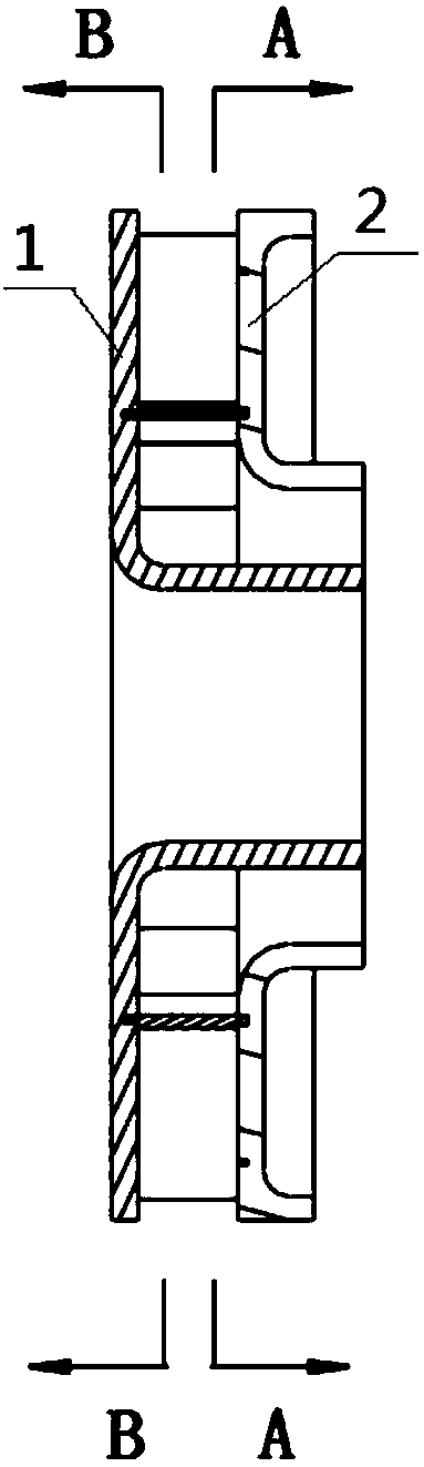
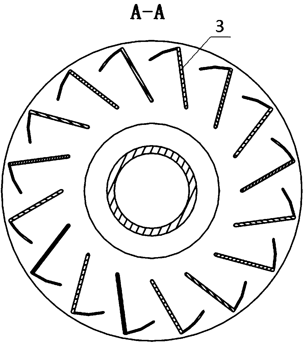
[0024] Referring to the figures, the variable flow cyclone includes a rotatable inner hub 1, a fixed outer hub 2 and rotatable blades 3; the rotatable inner hub 1 includes an inner hub bottom plate 7 and an inner hub outlet ring 6, and the inner hub bottom plate 7 There are several inner hub radial slides 4 arranged in a circular array, and several inner hub circumferential slides 5 arranged in a circular array; the fixed outer hub 2 includes an outer hub bottom plate 11 and an outer hub exit ring 10, and on the outer hub bottom plate 11 There are several outer hub rotating slideways 8 arranged in a circular array, and several outer hub rotating bearings 9 arranged in a circumferential array; the rotatable blade 2 includes a rotatable blade body 12, a first blade sliding shaft 13, a first blade rotating shaft 14, The second blade sliding shaft 15, the second blade rotating shaft 16; the first blade sliding shaft 13 is installed in the radial slideway 4 of the inner hub, and can...


PUM


Abstract

The invention belongs to the technical field of heat energy and power equipment and particularly relates to a variable flow whirlcone. The variable flow whirlcone comprises a rotatable inner hub, a fixed-type outer hub and rotatable blades, one sides of the rotatable blades are mounted on the fixed-type outer hub, and the other sides of the rotatable blades are mounted on the rotatable inner hub.The rotatable inner hub comprises an inner hub bottom plate and an inner hub outlet ring way, the fixed-type outer hub comprises an outer hub bottom plate and an outer hub outlet ring way, and the rotatable blades comprise rotatable blade bodies, first blade sliding shafts, first blade rotating shafts, second blade sliding shafts and second blade rotating shafts. According to the variable flow whirlcone, the blade mounting angle and the through flow area of the whirlcone can be changed, thus the flow of air entering the whirlcone and the swirling number can be changed, the defect that as for atraditional fixed-type whirlcone, the blade angle and the air flow cannot be adjusted is overcome, and non-detachable online adjustment of the whirlcone is achieved; and the time of shutting down forreplacing and test adjustment is saved, and the utilization rate of the variable flow whirlcone is increased.

Description

Technical field: [0001] The invention belongs to the technical field of thermal energy and power equipment, and in particular relates to a variable flow cyclone. Background technique: [0002] With the increasingly stringent environmental protection of oceans, ports and the atmosphere, countries around the world have put forward stricter and stricter limits on pollutant emissions from gas turbine combustors. In the compact space with high heat load in the combustor of ships and industrial gas turbines, in order to maintain high combustion efficiency and flame stability, and to achieve the required pollutant emission indicators, it is necessary to adopt low-emission combustion technology and control NOx at the same time and CO emissions. However, in conventional combustion chambers, the two are contradictory. How to reduce NOx emissions and ensure that CO emissions meet the standards in a wide range of working conditions is the main technical problem to be solved by the pre...

Claims


Application Information

Patent Timeline
Patent Type & Authority Applications(China)
IPC IPC(8): F23R3/14
CPCF23R3/14
Inventor 李雅军王之东张晨曦齐秀龙李名家
Owner 中国船舶重工集团公司第七0三研究所
Why Eureka
Try Eureka