Grain dryer

The technology of a grain dryer and a machine body is applied in the field of dryers, which can solve the problem of inconvenient switching on and off, and achieve the effects of efficiently drying grain, improving efficiency and saving time.

Inactive Publication Date: 2018-08-17
全椒金竹机械制造有限公司
View PDF5 Cites 0 Cited by
  • Summary
  • Abstract
  • Description
  • Claims
  • Application Information

AI Technical Summary

Problems solved by technology

When the traditional grain dryer is dry, it is easy to crush the grain. At the same time, t

Method used


Image

  • Grain dryer
  • Grain dryer
  • Grain dryer

Examples


Example Embodiment

[0021] The technical solutions in the embodiments of the present invention will be clearly and completely described below in conjunction with the accompanying drawings in the embodiments of the present invention. Obviously, the described embodiments are only a part of the embodiments of the present invention, rather than all the embodiments.

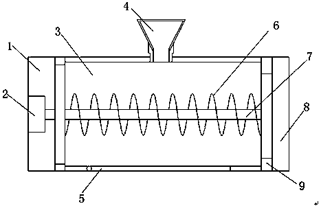
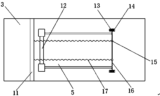
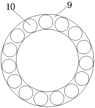
[0022] Reference Figure 1-4 , A grain dryer, comprising a body 1, a motor 2 is arranged inside the body 1, the output end of the motor 2 and one end of a rotating shaft 7 are fixed, a heating wire 6 is fixed on the rotating shaft 7, and one end of the heating wire 6 and a bearing One end of 9 is welded and fixed, the shape of the heating wire 6 is toroidal, the heating wire 6 is evenly distributed on the rotating shaft 7, one end of the rotating shaft 7 is inserted in the bearing 9, and the bearing 9 is installed inside the power block 8. And the contact point 10 is provided at the contact between the bearing 9 and the power block 8, the r...


PUM


Abstract

The invention discloses a grain dryer which comprises a machine body. A motor is arranged inside the machine body. The output end of the motor is fixedly connected with one end of a rotating shaft, and the rotating shaft is inserted into the middle of a bin body. A fixed shaft base is arranged at the bottom end of the bin body, and a fixing rod is inserted into the middle of the shaft base. A discharging plate is fixedly arranged on one side of the fixing rod. A pull rod is fixedly arranged on the other side of the discharging plate. One end of the pull rod is clamped in the middle of a rotating ring, and the rotating ring is fixedly installed inside a clamping block. The middle of the pull rod is fixedly sleeved with clamping rings, and one ends of the clamping rings are fixedly glued with one ends of elastic ropes. The other ends of the elastic ropes are fixedly glued with a fixing block. The fixing block is fixedly welded to the outer wall of the bin body. By adoption of the grain dryer, grains can be efficiently dried; and meanwhile the dried grains can be taken out quickly.

Description

technical field [0001] The invention relates to the technical field of dryers, in particular to a grain dryer. Background technique [0002] The grain dryer body is equipped with multiple drying chambers that can dry a variety of grains at the same time. The multiple drying chambers are arranged side by side. Each drying chamber is surrounded by a ventilating plate with mesh. Multiple drying chambers in the dryer body share one The heat recovery room and a ventilation channel, the heat recovery room is arranged in parallel above the ventilation channel, the bottom surface of the ventilation channel is open and directly communicates with each drying chamber, the heat recovery room is connected to the flue gas induced draft fan and the hot blast stove through the flue gas channel, and the ventilation channel is connected to the outside air cooler. When the traditional grain dryer is drying, it is easy to crush the grain. At the same time, the outlet of the bin body is fixed b...

Claims


Application Information

Patent Timeline
IPC IPC(8): F26B11/16F26B23/06F26B25/00A23B9/08
Inventor 史乾军史德才王海鸥孙艳辉史前彬张守军
Owner 全椒金竹机械制造有限公司
Why Eureka
Try Eureka