
Power equipment isolation safe sealing device

A technology for electrical equipment and sealing devices, applied in the directions of substation/switch layout details, electrical components, etc., can solve the problems of inconvenient use, weak practicability, poor isolation effect, etc., to ensure the sealing effect, work effect, and practicability. strong effect

Inactive Publication Date: 2018-08-17
陈书画
View PDF1 Cites 7 Cited by
  • Summary
  • Abstract
  • Description
  • Claims
  • Application Information

AI Technical Summary

Problems solved by technology

For example, the invention patent with the application number 201720841128.X includes a casing, an inner cavity is arranged inside the outer casing, a cooling box is arranged between the shielding layer and the inner cavity, a drawer is arranged inside the inner cavity, and the drawer There are several mounting brackets on one side of the surface. Although it solves the problem that the performance of the equipment cannot be improved, the isolation effect is poor, the working effect of the equipment cannot be guaranteed, the normal operation of the equipment is affected, the sealing effect of the equipment cannot be guaranteed, and multiple layers cannot be guaranteed. The sealing makes the equipment safer, and the sealing device cannot be easily disassembled and fixed. It is inconvenient to use and the problem of weak practicability still cannot be solved.

Method used


Image

  • Power equipment isolation safe sealing device
  • Power equipment isolation safe sealing device
  • Power equipment isolation safe sealing device

Examples


Embodiment Construction

[0014] The following will clearly and completely describe the technical solutions in the embodiments of the present invention with reference to the accompanying drawings in the embodiments of the present invention. Obviously, the described embodiments are only some, not all, embodiments of the present invention. Based on the embodiments of the present invention, all other embodiments obtained by persons of ordinary skill in the art without making creative efforts belong to the protection scope of the present invention.

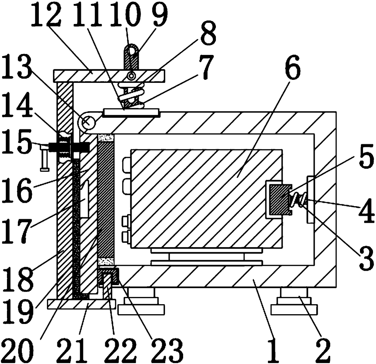
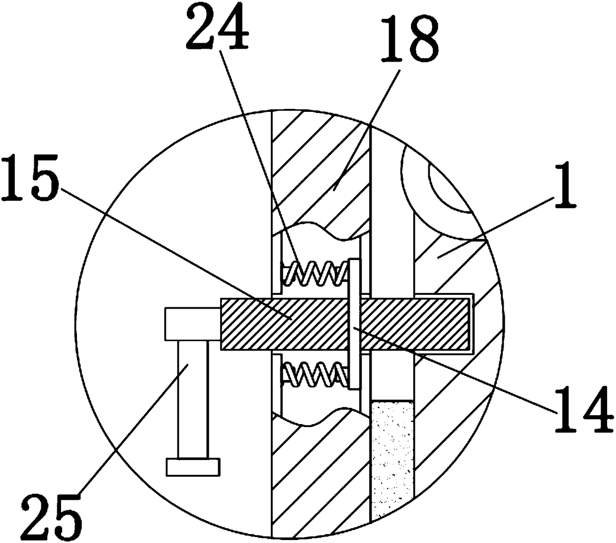
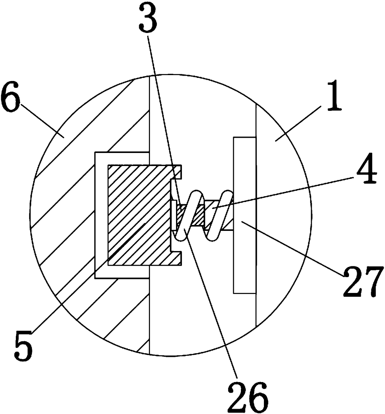
[0015] see Figure 1-3 , the present invention provides a technical solution: a safety sealing device for isolating electric equipment, including a box body 1 and an electric equipment 6, the box body 1 plays the role of protecting the electric equipment 6, and the lower end of the box body 1 is fixedly connected with a foot 2, The legs 2 play the role of supporting and protecting the box body 1. The inside of the box body 1 is fixedly connected with an electr...


PUM


Abstract

The invention discloses a power equipment isolation safe sealing device which comprises a housing and power equipment. A slide block is slidably snapped with a chute. The lower end of a pull rod is fixedly connected with a top board. A first spring sleeves the outer wall of the pull rod. An insertion rod penetrates through a vertical board and is snapped with the housing. The outer wall of the insertion rod is fixedly connected with a supporting board. The left side of each of the upper end and the lower end of the supporting board is fixedly connected with a second spring. According to the power equipment isolation safe sealing device, a sealing effect of the equipment is ensured through cooperation between the housing and a pin, cooperation between a snapping board and the vertical board, cooperation among the vertical board, a transverse board and a slide block chute, cooperation between the pull rod and a top block, function of the first spring, function of a sealing strip and a second sealing layer; higher safety of the equipment can be realized through multiple sealing layers; and the sealing device can be facilitated and detached through cooperation between the insertion rodand the supporting board and cooperation between the supporting board and the second spring. Furthermore the power equipment isolation safe sealing device has advantages of high convenience in use, and high practicability.

Description

technical field [0001] The invention relates to the technical field of electric equipment, in particular to an isolation safety sealing device for electric equipment. Background technique [0002] Power equipment mainly includes two categories: power generation equipment and power supply equipment. Power generation equipment is mainly power plant boilers, steam turbines, gas turbines, water turbines, generators, transformers, etc. Power supply equipment is mainly transmission lines of various voltage levels, transformers, contactors and more. The planned maintenance system adopted by most power equipment in the power system has serious defects, such as frequent temporary maintenance, insufficient or excessive maintenance, blind maintenance, etc., which makes countries in the world spend a lot of money on equipment maintenance every year. How to reasonably arrange the maintenance of power equipment, save maintenance costs, reduce maintenance costs, and at the same time ensur...

Claims


Application Information

Patent Timeline
Patent Type & Authority Applications(China)
IPC IPC(8): H02B1/46
CPCH02B1/46
Inventor 陈书画
Owner 陈书画
Learn More