Hematology bone marrow puncture needle

A bone marrow puncture and puncture needle technology, applied in the field of puncture needles, can solve the problems of affecting bone marrow collection, affecting bone marrow components, and the inability to accurately control the puncture depth, so as to achieve the effects of improving accuracy, improving purity, and improving safety

Pending Publication Date: 2018-08-21
WENZHOU CENT HOSPITAL
View PDF1 Cites 2 Cited by
  • Summary
  • Abstract
  • Description
  • Claims
  • Application Information

AI Technical Summary

Problems solved by technology

[0003] The collection tools used to collect bone marrow fluid are usually bone marrow puncture needles. The commonly used bone marrow puncture needles are not oriented accurately during puncture. After entering the bone marrow cavity, it passes out of the bone marrow cavity; at the same time, the volume of the extracted bone marrow is not precisely controlled, and the puncture depth cannot be precisely controlled. After searching and finding a patent with the application number CN201610682531.2, this patent solves the aforementioned problems to a certain extent. problems, but there are still defects: when the puncture needle tube in this patent is inserted into the human skin, the threaded ring on the lower surface of the puncture needle tube will outline and scratch the skin tissue, which will bring more pain to the patient; the threaded ring The needle hole used for bone marrow passage will also be blocked by human tissue, affecting the collection of bone marrow; at the same time, liquid from other human tissues flows into the puncture needle tube through the needle hole, affecting the bone marrow components collected later, and affecting the doctor's judgment on the patient's condition

Method used


Image

  • Hematology bone marrow puncture needle
  • Hematology bone marrow puncture needle
  • Hematology bone marrow puncture needle

Examples


Embodiment Construction

[0020] The present invention will be described in further detail below in conjunction with the embodiments given in the accompanying drawings.

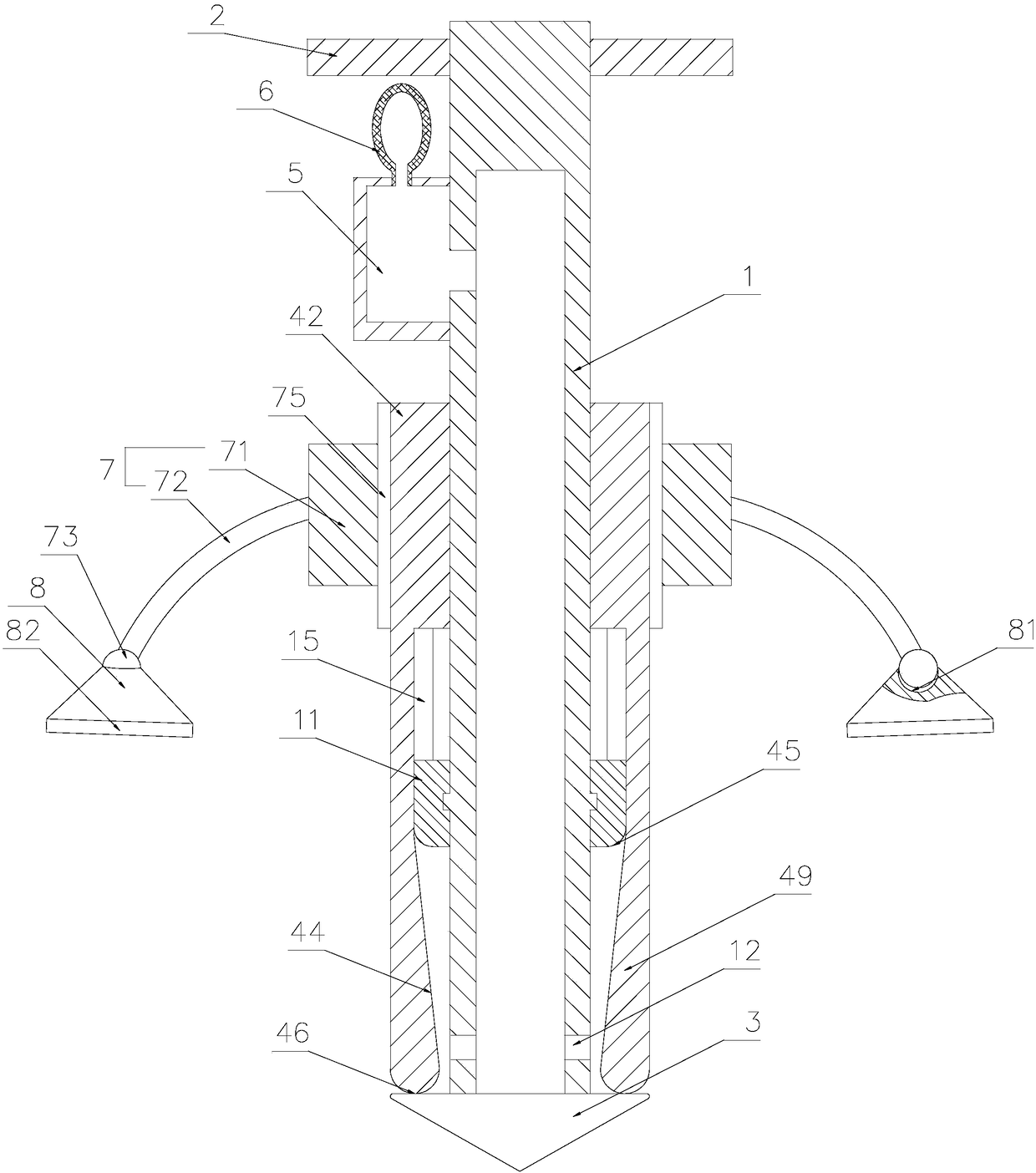
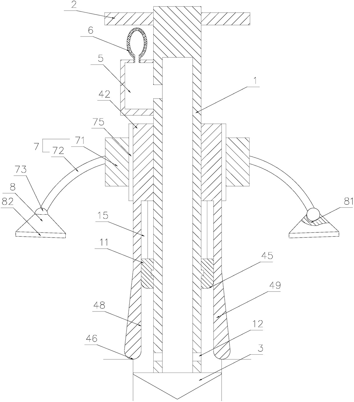
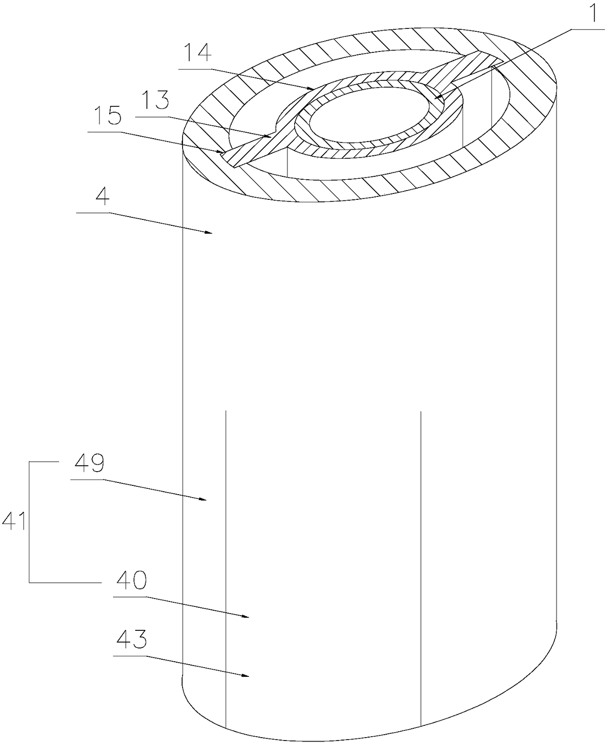
[0021] refer to Figure 1 to Figure 5 As shown, a hematology bone marrow puncture needle in this embodiment includes a puncture needle tube 1, one end of the puncture needle tube 1 is covered with a handle 2, the handle 2 is fixedly connected with the puncture needle tube 1, and the other end of the puncture needle tube 1 is connected with a needle 3. A pinhole 12 is provided on the side wall of the puncture needle tube 1 close to the needle head 3. The pinhole 12 communicates with the inner cavity of the puncture needle tube 1. A liquid storage tank 5 is provided on the side wall of the puncture needle tube 1 close to the handle 2. The liquid storage tank 5 communicates with the inner cavity of the puncture needle tube 1, and a negative pressure air bag 6 is installed on the top of the liquid storage tank 5. The working principle of ...


PUM


Abstract

The invention discloses a hematology bone marrow puncture needle. According to the technical scheme, the hematology bone marrow puncture needle includes a positioning ring and a positioning arm, wherein the inner ring wall of the positioning ring is slidably connected with a shield, and the shield sleeves a puncture needle tube, the positioning arm is arranged on the ring wall of the positioning ring and connected with an absorbing body, the diameter of the end face of a syringe needle connected with the puncture needle tube is larger than that of the puncture needle tube, the shield includesa fixed pipe and a plurality of deformation strips, the fixed pipe is connected with the puncture needle tube through a thread, the plurality of deformation strips extend in the axial direction of thepuncture needle tube and are connected with the end face of the fixed pipe, the other end of each of the plurality of deformation strips abuts against the end face of the syringe needle, the faces ofthe plurality of deformation strips towards the puncture needle tube are inclined surfaces, the diameter of an inner chamber of a deformation pipe is gradually reduced in the extension direction fromthe fixed pipe to the syringe needle, the outer wall of the puncture needle tube is also provided with a boss, the boss abuts against the inner wall of the deformation pipe, and the problem that other liquids are mixed in bone marrow collected by the puncture needle tube is solved.

Description

technical field [0001] The invention relates to a puncture needle, in particular to a hematology bone marrow puncture needle. Background technique [0002] Bone marrow aspiration is a common diagnostic technique for collecting bone marrow fluid. Clinically, bone marrow aspiration is also commonly used for blood cell morphology examination, and can also be used for hematopoietic stem cell collection, culture, cytogenetic analysis, and pathogenic biology inspection. [0003] The collection tools used to collect bone marrow fluid are usually bone marrow puncture needles. The commonly used bone marrow puncture needles are not oriented accurately during puncture. After entering the bone marrow cavity, it passes out of the bone marrow cavity; at the same time, the volume of the extracted bone marrow is not precisely controlled, and the puncture depth cannot be precisely controlled. After searching and finding a patent with the application number CN201610682531.2, this patent solve...

Claims


Application Information

Patent Timeline
IPC IPC(8): A61B10/02
CPCA61B10/025A61B10/0283A61B2010/0258
Inventor 陈松燕郑翠苹
Owner WENZHOU CENT HOSPITAL
Why Eureka
Try Eureka