Automatic material remover for punch

An automatic and punching technology, applied in the field of stamping equipment, can solve problems such as the failure of blanking to be discharged normally, easy to cause industrial accidents, and unfavorable production costs, so as to improve the effect of material return, avoid industrial accidents, and prolong the service life.

Pending Publication Date: 2018-08-21
中山市满一金属制品有限公司
View PDF0 Cites 0 Cited by
  • Summary
  • Abstract
  • Description
  • Claims
  • Application Information

AI Technical Summary

Problems solved by technology

[0002] Many stamping parts will produce blanking during the stamping and forming process. The blanking can be the waste that is punched and dropped from the product, or it can be the product that is punched and formed directly from the stamping belt. The blanking is generally It will fall directly from the blanking port of the stamping die to the bottom of the stamping die. When the blanking material under the stamping die accumulates a lot, it generally needs to be cleaned or collected manually. Otherwise, the blanking material will accumulate at the blanking port, making subsequent The blanking during the stamping process cannot be discharged normally, which affects the continuation of production; due to the high speed of the punching machine, in order to ensure safety, the blanking under the blanking port must be cleaned or collected after the punching machine is stopped, which will Affects efficiency, and it will take up more human resources, which is not conducive to reducing production costs; and when the blanking is a product, it is collected by manual use of fixtures in many cases, which is more dangerous and easy to cause industrial accidents

Method used


Image

  • Automatic material remover for punch
  • Automatic material remover for punch
  • Automatic material remover for punch

Examples


Embodiment Construction

[0023] The following will clearly and completely describe the technical solutions in the embodiments of the present invention with reference to the drawings in the embodiments of the present invention.

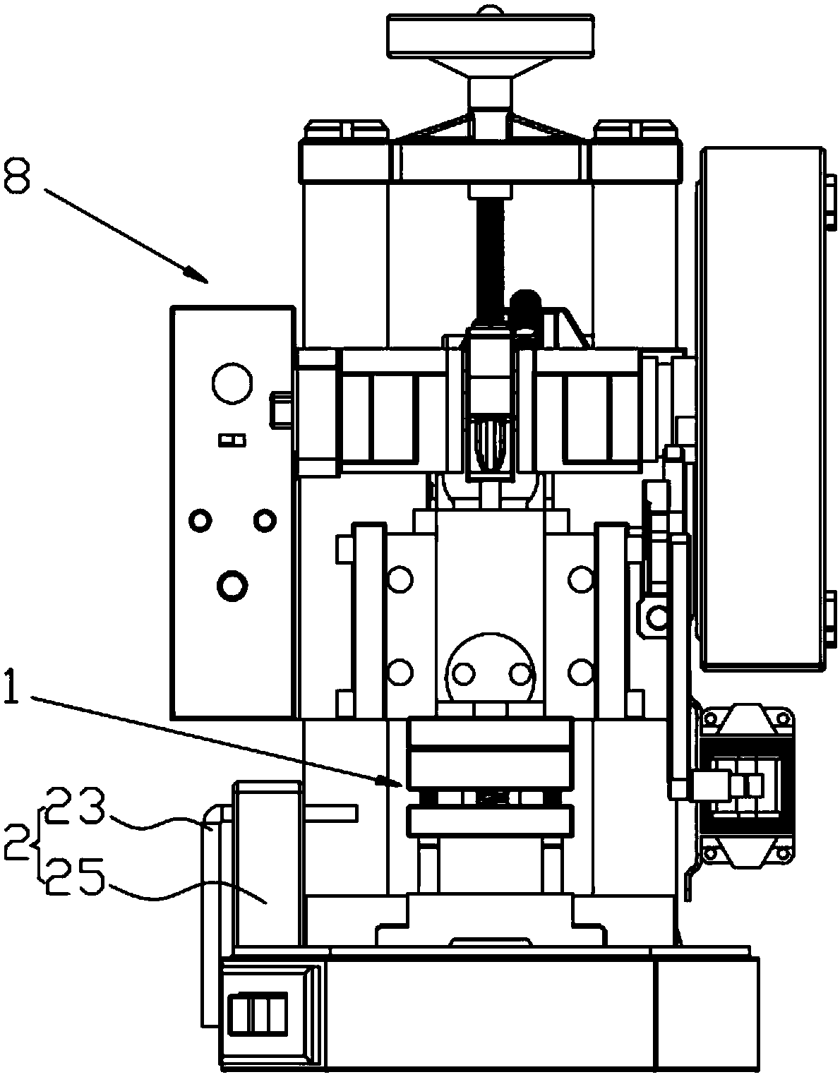
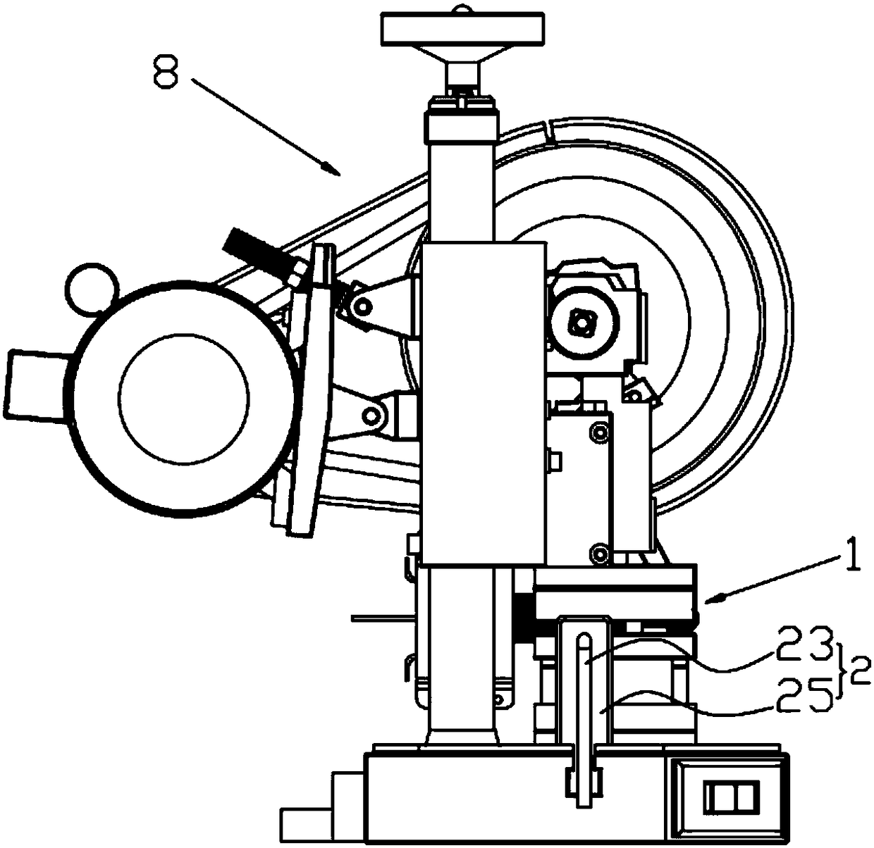
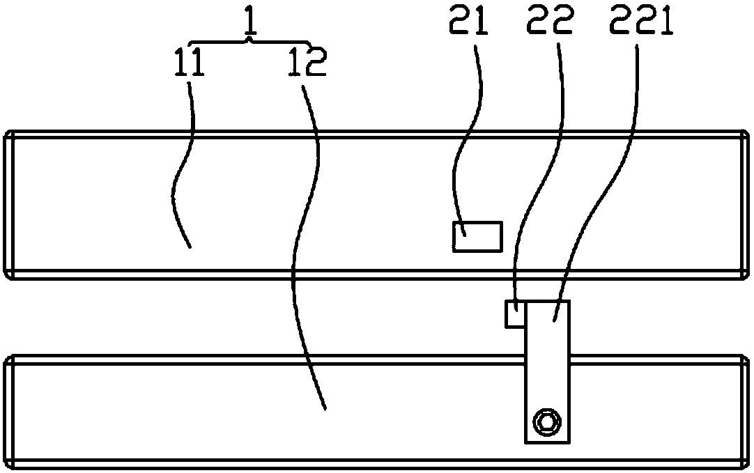
[0024] like Figure 1~4 As shown, an automatic ejection device for a punch provided by an embodiment of the present invention includes an air blowing device 2 for blowing the blank below the blanking opening of the stamping die 1 out of the stamping die 1 from one side of the stamping die 1, and the blowing device 2 and The solenoid valve (not shown) is connected, and the solenoid valve is connected with the proximity sensor 21. The proximity sensor 21 is fixed on the upper mold 11 side of the stamping die 1, and the proximity sensor 21 side is provided with an induction insert for inductively connecting with it when the mold is closed. 22. In this embodiment, the induction insert 22 is fixed on the vertical rod 221, and the vertical rod 221 is fixedly connected to the side of...


PUM


Abstract

The invention relates to an automatic material remover for a punch. The automatic material remover comprises a blower for blowing a falling material under a material falling outlet of a punch die outof the punch die from one side of the punch die, wherein the blower is connected to an electromagnetic valve, the electromagnetic valve is connected to a proximity sensor, the proximity sensor is fixed on one side of an upper die of the punch die, a sensing insert which is used for being in sensing connection with the proximity sensor during die closing is arranged at one side of the proximity sensor, and the sensing insert is fixed with one side of a lower die of the punch die. The blower can blow a material falling from the material falling outlet of the punch die out of the punch die at themoment when the punch die is closed, the proximity sensor can cooperate with the sensing insert to control the blower to open at the moment when the punch die is closed, so that the blower can be prevented from being in a normally opened state, consequently, the energy consumption of the blower can be reduced, and the service life of the blower can be prolonged; the falling material can be more easily blown away by the blower in the process of falling, so that the material removal effect can be improved, consequently, manual material removal can be thoroughly replaced, the efficiency can be conveniently increased, the cost is reduced, and safety is ensured.

Description

technical field [0001] The invention belongs to the technical field of punching equipment, and in particular relates to an automatic material return device for a punching machine. Background technique [0002] Many stamping parts will produce blanking during the stamping and forming process. The blanking can be the waste that is punched and dropped from the product, or it can be the product that is punched and formed directly from the stamping belt. The blanking is generally It will fall directly from the blanking port of the stamping die to the bottom of the stamping die. When the blanking material under the stamping die accumulates a lot, it generally needs to be cleaned or collected manually. Otherwise, the blanking material will accumulate at the blanking port, making subsequent The blanking during the stamping process cannot be discharged normally, which affects the continuation of production; due to the high speed of the punching machine, in order to ensure safety, the...

Claims


Application Information

Patent Timeline
IPC IPC(8): B21D45/00
CPCB21D45/006
Inventor 王德彩朱俊
Owner 中山市满一金属制品有限公司
Why Eureka
Try Eureka