Hydraulic index chuck

An indexing chuck, hydraulic technology, applied in the direction of chuck, clamping, support, etc., can solve the problems of increasing the clamping force, reducing the service life of the chuck, easily exceeding the tensile strength of the chuck, etc., to avoid clamping Loss of tightening force, ensuring stable clamping effect

Pending Publication Date: 2018-08-21
宁波迈途机械科技有限公司
View PDF0 Cites 3 Cited by
  • Summary
  • Abstract
  • Description
  • Claims
  • Application Information

AI Technical Summary

Problems solved by technology

During the workpiece processing, the clamping seat and the fixture will generate a centrifugal force with the rotation movement. If the rotational speed reaches a certain level and the centrifugal force is greater than the hydraulic clamping force, the workpiece will easily be in the state of not being clamped, causing the workpiece to vibrate the tool easily. , so as to cause damage to the surface of the workpiece. In severe cases, the workpiece may fly out of the chuck, resulting in production accidents
At present, there are generally two kinds of solutions: one is to increase the clamping force by increasing the clamping area of ​​the chuck, which is equivalent to increasing the chuck and increasing the overall weight of the chuck. It is used in small The machine tool will seriously affect the spindle speed; the other is to increase the clamping force by increasing the output pressure of the hydraulic station. This method is easy to exceed the tensile strength of the chuck, and long-term use will definitely reduce the service life of the chuck.

Method used


Image

  • Hydraulic index chuck
  • Hydraulic index chuck
  • Hydraulic index chuck

Examples


Embodiment Construction

[0024] The present invention will be further described in detail below in conjunction with the accompanying drawings and embodiments.

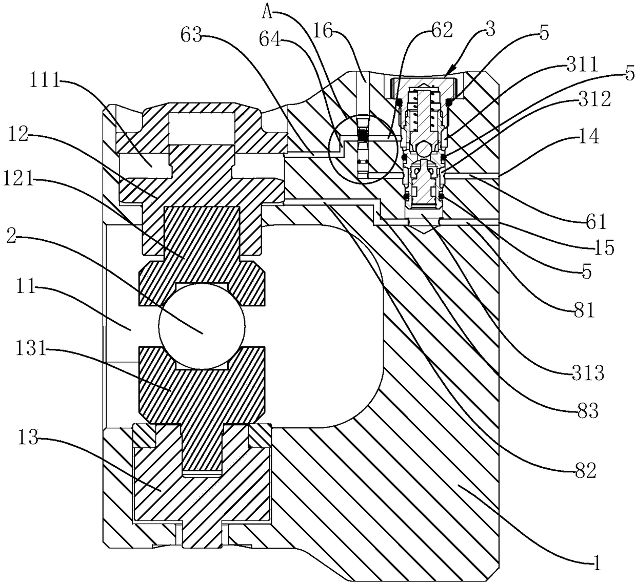
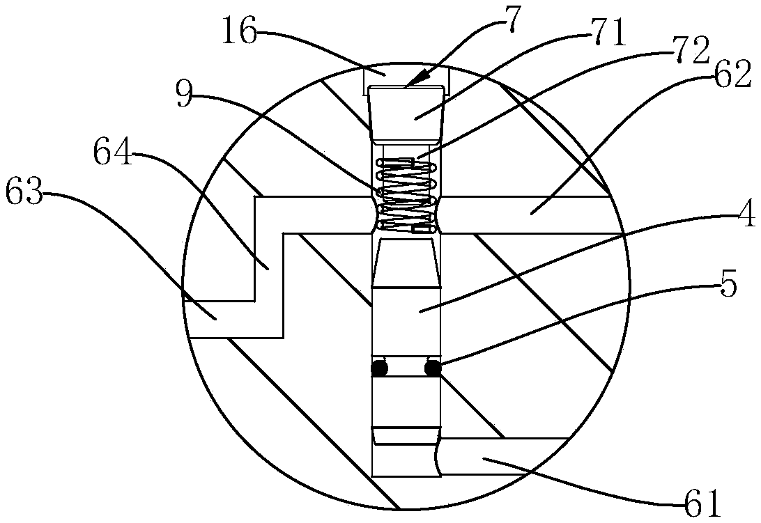
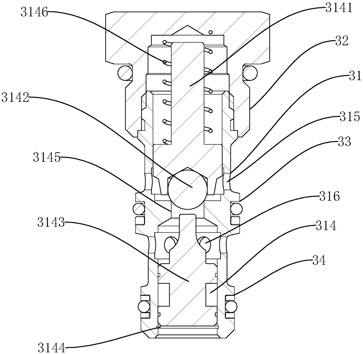
[0025] Such as Figure 1 to Figure 3 As shown, a hydraulic indexing chuck includes a chuck body 1, a clamping cavity 11 is provided in the front end of the chuck body 1, and an upper clamping seat 12 and a lower clamping seat 12 opposite up and down are arranged in the clamping cavity 11. The seat 13, the upper clamping seat 12 and the lower clamping seat 13 are respectively provided with an upper clamp 121 and a lower clamp 131 for clamping the workpiece 2, and the upper clamping base 12 can be moved up and down in the clamping cavity 11, The lower clamping seat 13 is fixedly arranged in the clamping cavity 11, and the chuck body 1 is provided with a hydraulic oil circuit for controlling the upper clamping seat 12 to clamp the workpiece 2 downward or to release the workpiece 2 upward. There is a pressure compensation mechanism.

[0026]In t...


PUM


Abstract

The invention discloses a hydraulic index chuck which comprises a chuck body. A clamping cavity is formed in the front end of the chuck body, an upper clamping seat and a lower clamping seat are arranged in the clamping cavity and vertically opposite, an upper clamp and a lower clamp for clamping workpieces are arranged in the upper clamping seat and the lower clamping seat, the upper clamping seat is vertically and movably arranged in the clamping cavity, the lower clamping seat is fixedly arranged in the clamping cavity, and a hydraulic circuit for controlling the upper clamping seat to clamp workpieces downwards or release the workpieces upwards is arranged on the chuck body. The hydraulic index chuck is characterized in that a pressure compensation mechanism is arranged on the hydraulic circuit. The hydraulic index chuck has the advantages that the pressure compensation mechanism arranged on the hydraulic circuit provides a reverse centrifugal force, pressure compensation for the upper clamping seat is realized, loss of clamping force caused by the centrifugal force of the clamping seats and the clamps can be avoided, stable clamping of the workpieces is ensured, and the hydraulic index chuck is simple in structure and good in safety.

Description

technical field [0001] The invention relates to an indexing chuck, in particular to a hydraulic indexing chuck. Background technique [0002] The indexing chuck is a high-precision clamping tool used on a CNC lathe. It is used to clamp the workpiece and can be rotated according to the requirements, so that multiple surfaces of the workpiece can be clamped in one clamping. processed to. According to the clamping power source, the indexing chuck can be divided into electric indexing chuck, pneumatic indexing chuck and hydraulic indexing chuck. [0003] The hydraulic indexing chuck uses hydraulic pressure for clamping and indexing. The conventional hydraulic indexing chuck includes a chuck body. The lower clamping seat, the upper clamping seat and the lower clamping seat are respectively fixed with fixtures for clamping the workpiece. The lower clamping seat is fixed in the clamping cavity, and the upper clamping seat can be moved up and down through the control of the hydrau...

Claims


Application Information

Patent Timeline
Patent Type & Authority Applications(China)
IPC IPC(8): B23B31/10B23Q3/08B23Q16/10
CPCB23B31/10B23Q3/08B23Q3/082B23Q16/10
Inventor 潘峰
Owner 宁波迈途机械科技有限公司
Why Eureka
Try Eureka