Chamfering machine

A technology of a chamfering machine and a base, applied in the field of chamfering machines, can solve the problems of low chamfering accuracy, easy to bruise workers, low chamfering efficiency, etc., to improve chamfering accuracy, facilitate chamfering, and save costs Effect

Active Publication Date: 2018-08-21
庐山市环绿时代农业科技开发有限公司
View PDF8 Cites 1 Cited by
  • Summary
  • Abstract
  • Description
  • Claims
  • Application Information

AI Technical Summary

Problems solved by technology

The applicant found that the existing chamfering machines often have the following problems during use: (1) The existing chamfering machines usually perform chamfering operations on the operating table, and the remaining waste remains on the operating table after chamfering , it needs to be cleaned manually regularly, which is troublesome, and the waste chips are generally under the tool, which is easy to hurt the worker; (2) when the existing chamfering machine chamfers the plate, the chamfering accuracy is often not high, The problem of low chamfering efficiency

Method used


Image

  • Chamfering machine
  • Chamfering machine
  • Chamfering machine

Examples


Embodiment Construction

[0019] In order to make the structure and principle of the present invention clearer, the present invention will be described in detail below in conjunction with the accompanying drawings and specific embodiments:

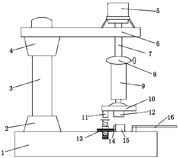
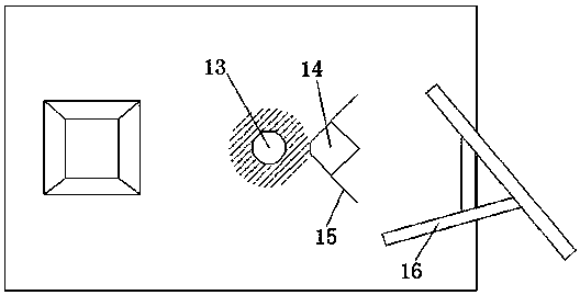
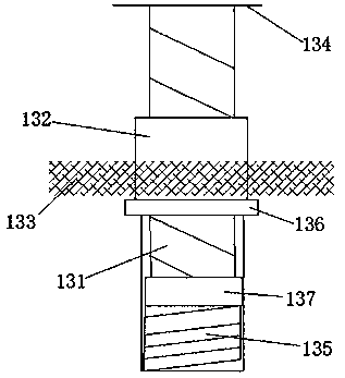
[0020] like figure 1 , 2 , 3, a chamfering machine, including a base 1, one end above the base 1 is provided with a support seat 2, the upper end of the support seat 2 is provided with a support frame 3 along the axial direction of the support seat 1, the support frame 3 The upper end of the lifting seat 4 is provided with a lifting seat 4, and the lifting seat 4 is provided with a weighing beam 6. The driving device 5 is provided on the weighing beam 6, and the driving device 5 is provided with a lifting rail 7 along the axial direction of the driving device. The lifting rail 7 is located on the drive The lower end of the device 5, the lower end of the lifting rail 7 is provided with an adjusting part 8, the lower end of the adjusting part 8 is fixedly provided w...


PUM


Abstract

The invention relates to a chamfering machine. A support base is arranged at one end above a chamfering machine base; a support rack is arranged at the upper end of the support base; a lifting base isarranged at the upper end of the support rack; a balance beam is arranged on the lifting base; a driving device is arranged on the balance beam; a lifting track is arranged on the driving device; anadjusting component is arranged at the lower end of the lifting track; a lifting rod is arranged at the lower end of the adjusting component; a fixing base is arranged at the lower end of the liftingrod; a pressing block and a cutter are arranged on the lower end surface of the fixing base; the other end above the base is an operation platform; a cleaning device and a square spacer are arranged on the operation platform; the cleaning device is positioned right below the pressing block; burr is arranged on the edge below the cleaning device; when being extruded by the pressing block downwards,the cleaning device can rotate to clean chamfering sweeps; limiting plates matched with a chamfered plate are respectively arranged on two sides of chamfering sides of the spacer; the heights of thelimiting plates are greater than that of the spacer. By adopting the chamfering machine, sweeps can be conveniently cleaned, and particularly plate-shaped articles can be conveniently chamfered.

Description

technical field [0001] The invention relates to the technical field of mechanical equipment, in particular to a chamfering machine. Background technique [0002] Chamfering is to remove the burrs on the parts due to machining, and to facilitate the assembly of parts, it is generally chamfered at the end or edge of the part. The applicant found that the existing chamfering machines often have the following problems during use: (1) The existing chamfering machines usually perform chamfering operations on the operating table, and the remaining waste remains on the operating table after chamfering , it needs to be cleaned manually regularly, which is troublesome, and the waste chips are generally under the tool, which is easy to hurt the worker; (2) when the existing chamfering machine chamfers the plate, the chamfering accuracy is often not high, The problem of low chamfering efficiency. Contents of the invention [0003] In view of the above problems, the object of the pre...

Claims


Application Information

Patent Timeline
Patent Type & Authority Applications(China)
IPC IPC(8): B23D79/00B23Q11/00
CPCB23D79/00B23Q11/0042
Inventor 杜诗
Owner 庐山市环绿时代农业科技开发有限公司
Why Eureka
Try Eureka