Automatic feeder for laser engraving machine

A technology of automatic feeding and laser engraving machine, applied in the field of machinery, can solve the problems of low efficiency, time-consuming and laborious, and achieve the effect of ensuring orderliness, improving production efficiency, and small size

Pending Publication Date: 2018-08-21
SUZHOU LINGYU ELECTRONICS TECH CO LTD
View PDF0 Cites 1 Cited by
  • Summary
  • Abstract
  • Description
  • Claims
  • Application Information

AI Technical Summary

Problems solved by technology

In the prior art, when 3C parts are marked by laser engraving, the parts are placed on the jig manually, which is time-consuming and

Method used


Image

  • Automatic feeder for laser engraving machine
  • Automatic feeder for laser engraving machine
  • Automatic feeder for laser engraving machine

Examples


Embodiment Construction

[0032] Attached below Figure 1-13 The present invention is described in further detail.

[0033] The material of the present invention is a part of a 3C product, and is characterized by small volume and light weight.

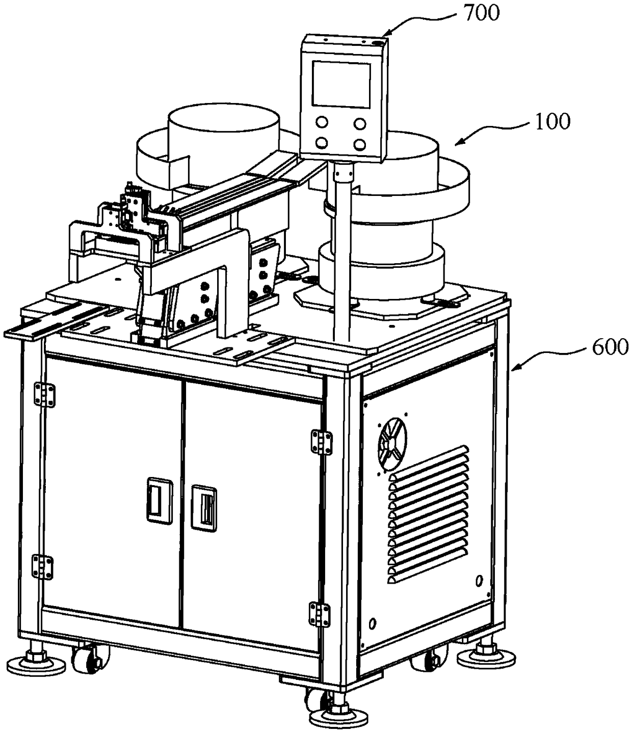
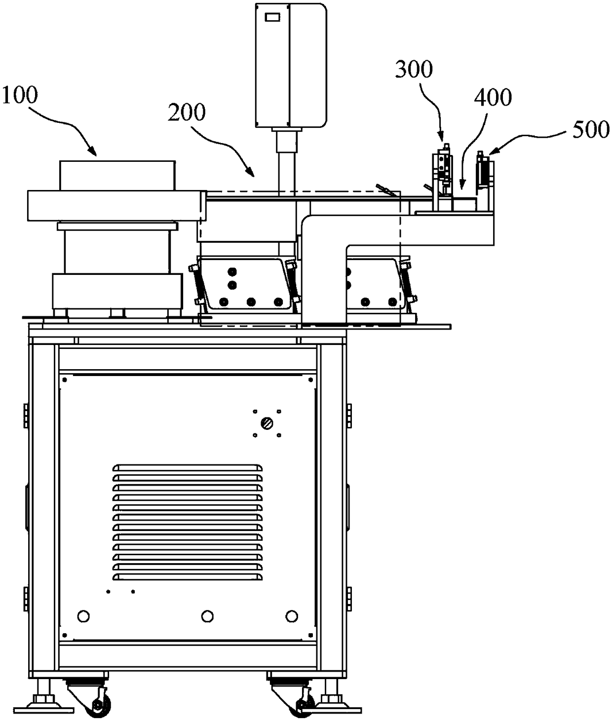
[0034] refer to Figure 1-13 , an automatic feeding machine for a laser engraving machine, including a vibrating plate 100, a feeding unit 200, a feeding unit 300, a jig 400 and a discharging unit 500 arranged in sequence;

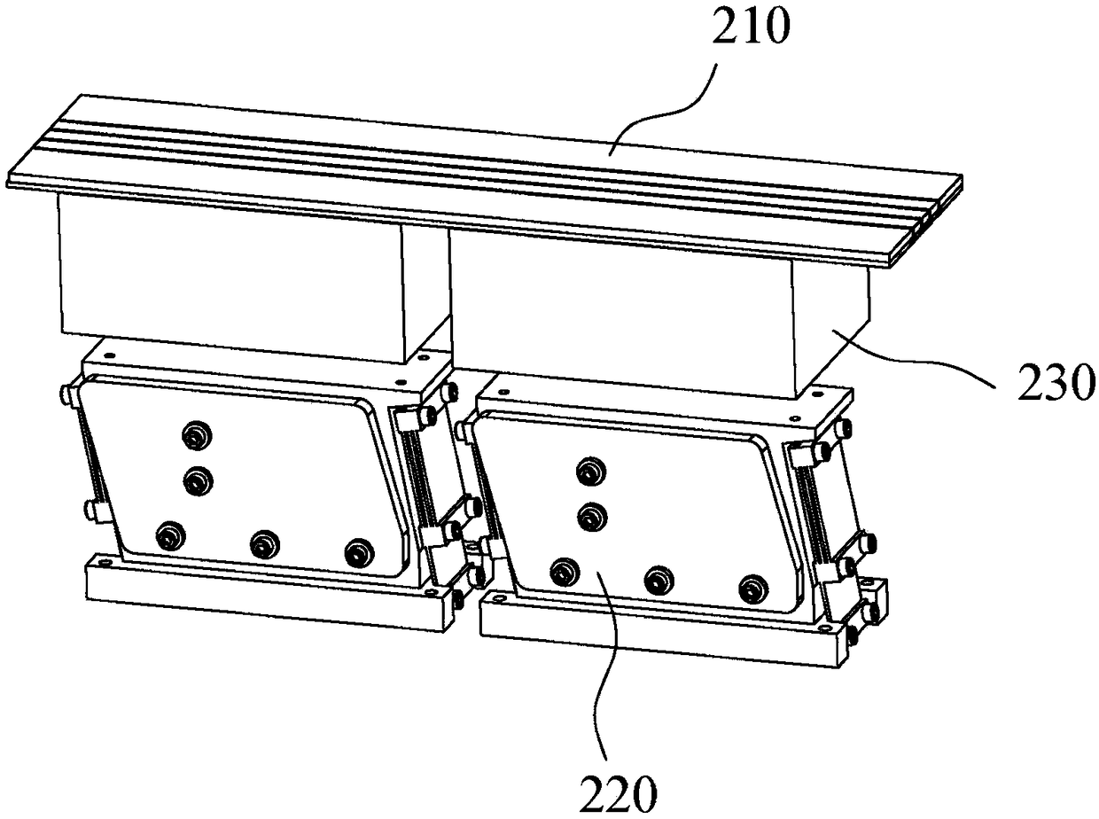
[0035] The feeding unit 200 includes a first material guide 210 and a straight vibrator 220, and the first material guide 210 is provided with a plurality of first material guide grooves 211 that regulate the linear movement trajectory of the material;

[0036] The feeding unit 300 includes a first air nozzle 310, a second material guide 320 and a pressure head 330 that can be raised and lowered. The second material guide 320 is provided with a second material guide 321 connected to the first material guide 211, The pressure head 330 can...


PUM


Abstract

The invention provides an automatic feeder for a laser engraving machine. The automatic feeder comprises a vibrating tray, a supply unit, a feed unit, a jig and a discharge unit arranged in sequence;the supply unit comprises a first guide part and a linear vibrator, and the first guide part is provided with a plurality of first guide grooves which specify a linear motion track for materials; thefeed unit comprises a first air nozzle, a second guide part, and pressing heads capable of moving up and down, the second guide part is provided with second guide grooves connected to the first guidegrooves, the pressing heads can get into and out of the second guide grooves, the first air nozzle faces toward the first guide grooves, and has a blowing direction deflected to a feed direction; thejig is provided with third guide grooves connected to the second guide grooves; the discharge unit comprises a second air nozzle and a blocking plate capable of moving up and down, the second air nozzle faces toward the second guide grooves, and has a blowing direction deflected to a discharge direction. The automatic feeder for the laser engraving machine, disclosed by the invention, can carry out automatic feeding, increasing the efficiency of production, reducing manpower, and greatly reducing production cost.

Description

technical field [0001] The invention relates to the technical field of machinery, in particular to an automatic feeding machine for a laser engraving machine. Background technique [0002] With the increasing shipments of 3C products, the demand for components is also increasing. 3C parts have the characteristics of light weight, small size and large quantity. In the prior art, when 3C parts are marked by laser engraving, the parts are placed on the jig manually, which is time-consuming and laborious. It requires the cooperation of multiple people to complete the laser engraving production, and the efficiency is very low. Contents of the invention [0003] Aiming at the above-mentioned defects of the prior art, the present invention provides an automatic feeding machine for laser engraving machines. [0004] According to one aspect of the present invention, an automatic feeding machine for a laser engraving machine is provided, including a vibrating plate, a feeding unit...

Claims


Application Information

Patent Timeline
IPC IPC(8): B23K26/70B23K26/362
CPCB23K26/702B23K26/361
Inventor 黄峰
Owner SUZHOU LINGYU ELECTRONICS TECH CO LTD
Why Eureka
Try Eureka