
Tunnel drilling construction equipment

A technology for construction equipment and tunnels, used in metal processing equipment, metal processing, manufacturing tools, etc., can solve the problems of difficult connection between casing and thread, low difficulty in connecting casing and thread, and low labor intensity.

Inactive Publication Date: 2018-08-21
张茂排
View PDF0 Cites 1 Cited by
  • Summary
  • Abstract
  • Description
  • Claims
  • Application Information

AI Technical Summary

Problems solved by technology

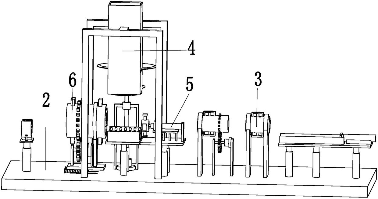
[0004] In order to solve the above problems, the present invention provides a tunnel drilling construction equipment, which can solve the problems of high labor intensity, danger of manual operation, and manual connection of threaded fasteners and casings during casing installation by the existing pipe shed method. , The connection error between the casing and the threaded button is large, and the connection between the casing and the threaded button is difficult; it can realize the automatic positioning connection between the casing and the threaded button, and the automatic feeding of the threaded button. It has low labor intensity and no danger for automatic installation. The advantages of high reliability, automatic connection between the threaded button and the bushing, small connection error between the bushing and the threaded button, and little difficulty in connecting the bushing and the threaded button, etc.

Method used


Image

  • Tunnel drilling construction equipment
  • Tunnel drilling construction equipment
  • Tunnel drilling construction equipment

Examples


Embodiment Construction

[0029] In order to make the technical means, creative features, goals and effects achieved by the present invention easy to understand, the present invention will be further described below in conjunction with specific illustrations. It should be noted that, in the case of no conflict, the embodiments in the present application and the features in the embodiments can be combined with each other.

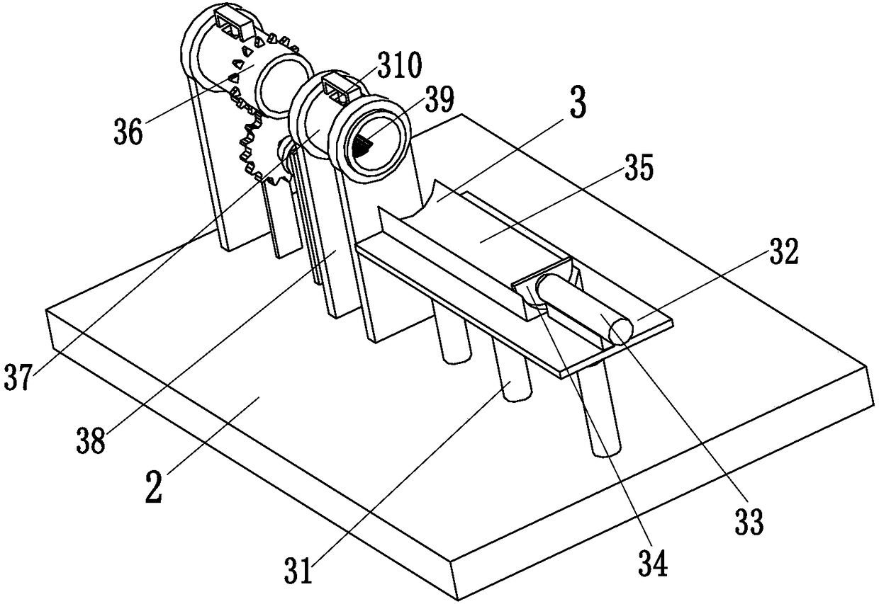
[0030] Such as Figure 1 to Figure 8 As shown, a tunnel drilling construction equipment includes a supporting base plate 2, a pipeline pushing device 3, a feeding device 4, a threaded button pushing device 5 and a threaded button installation device 6, and the supporting base plate 2 is symmetrically provided with two A chute, the pipeline pushing device 3 is installed on the left end top of the supporting base plate 2, the unloading device 4 is connected with the middle upper end surface of the supporting base plate 2, the threaded button pushing device 5 is located under the unload...


PUM


Abstract

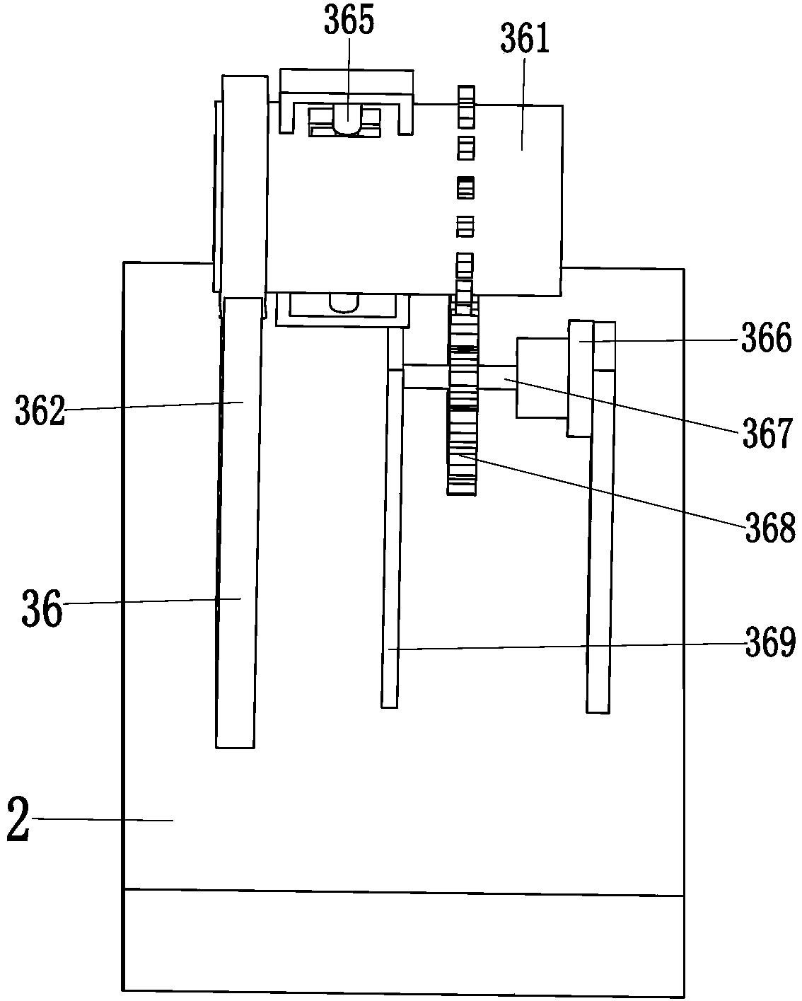
The invention relates to tunnel drilling construction equipment. The tunnel drilling construction equipment comprises a supporting bottom plate, a pipeline pushing device, a discharging device, a screw thread pushing device and a screw thread installing device. The pipeline pushing device is arranged on the top of the left end of the supporting bottom plate, and the discharging device is connectedwith the upper end face of the middle portion of the supporting bottom plate. The screw thread pushing device is located below the discharging device and arranged on the top of the supporting bottomplate. The screw thread installing device is connected with the top of the left end of the supporting bottom plate. The pipeline pushing device comprises a pipeline supporting push rod, a pushing support plate, a pushing push rod, a pushing plate, an arc support, a pipeline rotation mechanism, a pipeline clamping sleeve, a supporting bearing frame, a clamping plate and a clamping plate push rod. The tunnel drilling construction equipment can solve the problems that during tubular running construction through an existing pipe shed method, the labor intensity is large, risks exist due to manualoperation, screw thread and casing pipe connection is manually conducted, the casing pipe and screw thread connection error is large, and the casing pipe and screw thread connecting difficulty is large.

Description

technical field [0001] The invention relates to the technical field of tunnel construction, in particular to tunnel drilling construction equipment. Background technique [0002] The tube shed method construction or the umbrella arch method is an advanced support structure for shallow buried underground excavation of underground structural engineering. A steel pipe with a large moment of inertia is installed in the hole, which acts as a temporary advance support to prevent the soil layer from collapsing and surface subsidence, so as to ensure the safe operation of excavation and subsequent processes; As a new technology for tunneling in surrounding rocks, the pipe shed method was first used as an auxiliary method for tunnel construction. It played an important role in the construction of soft rock tunnels through broken zones, loose zones, and weak strata, and water and sand gushes. Since the pre-buried advanced pipe shed as roof and side wall support has laid a solid found...

Claims


Application Information

Patent Timeline
IPC IPC(8): B23P19/06
CPCB23P19/06B23P19/001
Inventor 张茂排
Owner 张茂排
Learn More