A middle section connecting device of a rotating part

A technology for connecting devices and rotating parts, applied in electromechanical devices, electric components, electrical components, etc., can solve the problems of inconvenient disassembly and maintenance, poor adaptability, inconvenient disassembly and installation, etc., to reduce maintenance costs, reduce connection errors, and facilitate disassembly The effect of maintenance

Active Publication Date: 2022-08-02
FUZHOU SIFEI INFORMATION TECH CO LTD
View PDF9 Cites 0 Cited by
  • Summary
  • Abstract
  • Description
  • Claims
  • Application Information

AI Technical Summary

Problems solved by technology

[0007] The purpose of the present invention is to provide a connecting device for the middle part of the rotating part to solve the inconvenient positioning and connection proposed in the above-mentioned background technology. The common middle connecting device cannot locate the rotating part, so that there is a certain connection error when the parts are connected. It takes a lot of time to adjust the position of the rotating parts, and it is not easy to disassemble and install. The whole device adopts an integrated structure, which is not conducive to the disassembly and transportation of the device, and it is not convenient to disassemble and repair the various parts of the device. Once a certain part fails Or damaged, it needs to be replaced as a whole. At the same time, it is not convenient to replace the connection position according to the actual situation, which makes the overall adaptability of the device poor, which is not conducive to the problem that the connection device can adapt to the rotation of different dimensions.

Method used


Image

  • A middle section connecting device of a rotating part
  • A middle section connecting device of a rotating part
  • A middle section connecting device of a rotating part

Examples


Embodiment Construction

[0029] The technical solutions in the embodiments of the present invention will be clearly and completely described below with reference to the accompanying drawings in the embodiments of the present invention. Obviously, the described embodiments are only a part of the embodiments of the present invention, but not all of the embodiments. Based on the embodiments of the present invention, all other embodiments obtained by those of ordinary skill in the art without creative efforts shall fall within the protection scope of the present invention.

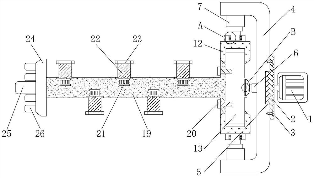
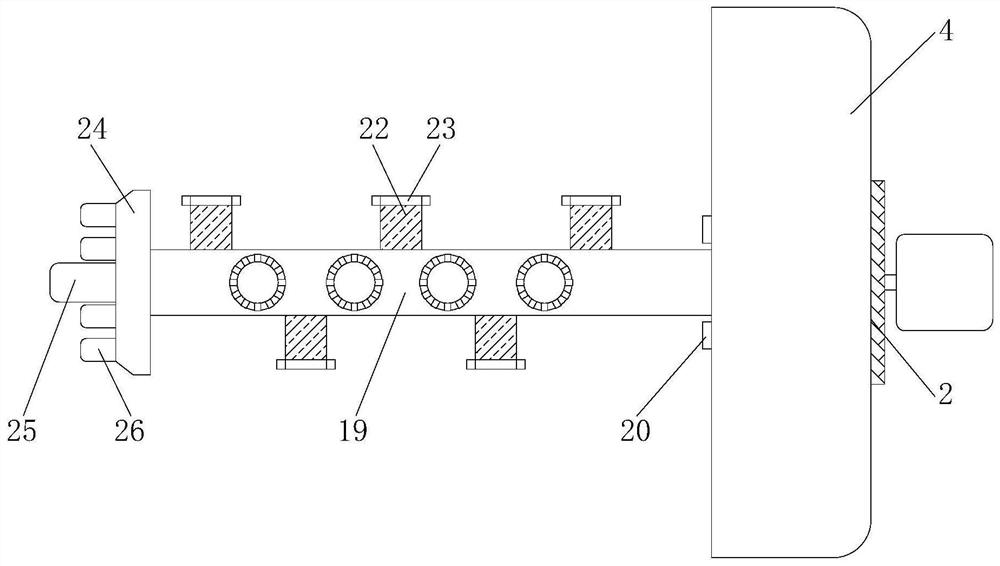
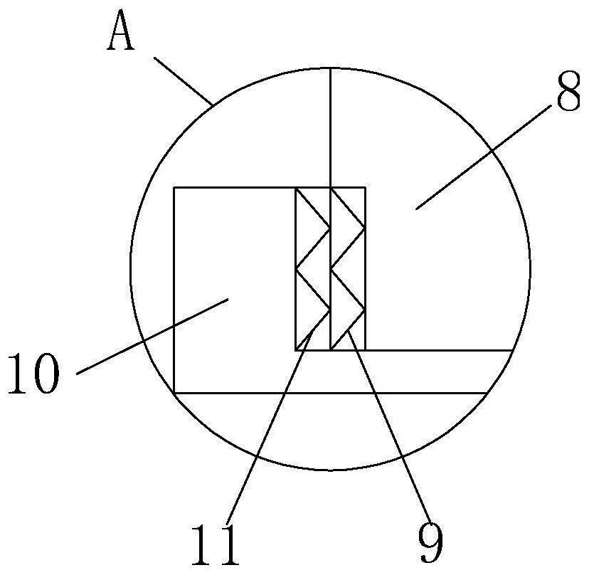
[0030] see Figure 1-7, the present invention provides a technical solution: a middle section connecting device of a rotating component, comprising a first motor 1, a connecting plate 2, an embedded screw 3, a limit chuck 4, a limit slot 5, a miniature telescopic rod 6, an electric pusher Rod 7, connecting rod 8, external thread 9, connecting block 10, internal thread 11, special-shaped block 12, gear plate 13, magnet ring 14, infrare...


PUM


Abstract

The invention discloses a middle section connecting device of a rotating component, comprising a first motor, an output shaft of the first motor is fixedly connected with a connecting plate through a coupling, and one side of the connecting plate is threadedly connected with an embedded screw, and is connected to The other side of the disk is fixedly connected with a limit chuck, and the outer wall of the limit chuck is provided with a limit slot. The middle-section connection device of the rotating part is provided with a magnet ring and an infrared induction chip. When the iron suction cup is adsorbed on the magnet ring, and the infrared induction chip senses the light of the infrared lamp bead, it controls the electric push rod to drive the special-shaped block to clamp the gear disc. Connect, then shrink the miniature telescopic rod, so that the iron suction cup is separated from the magnet ring, the middle section connecting device of the rotating part is convenient for positioning and connecting, and the improved middle section connecting device can locate the rotating parts, which greatly reduces the connection error when the parts are connected. It is small and does not need to waste a lot of time to adjust the position of the rotating parts, which brings more convenience to the use of the connecting device.

Description

technical field [0001] The invention relates to the technical field of connecting devices, in particular to a middle-section connecting device of a rotating component. Background technique [0002] A component is a part of a device system, which is composed of several components assembled together. In the process of mechanical assembly, these components are first assembled into components (component assembly), and then enter the general assembly. Parts) are assembled with other parts and components into larger parts before entering the general assembly, which are assembled from several sub-parts and have independent functions. The assembly, any device is composed of multiple components, and the different components are connected by connecting devices. The components used to control the rotation of the total device are called rotating components. Generally, the connection of rotating components is performed by interrupting the connecting device. There are still some defects ...

Claims


Application Information

Patent Timeline
Patent Type & Authority Patents(China)
IPC IPC(8): F16D1/06H02K7/10
CPCF16D1/06H02K7/10
Inventor 董恺
Owner FUZHOU SIFEI INFORMATION TECH CO LTD
Why Eureka
Try Eureka