A Path Planning Method for 3D Point Cloud Surface Divided by Discontinuous Grid

A 3D point cloud and path planning technology, which is applied in manufacturing auxiliary devices, processing data acquisition/processing, additive processing, etc. Quantity, guaranteed accuracy, and strong applicability

Active Publication Date: 2019-12-24
XI AN JIAOTONG UNIV
View PDF7 Cites 0 Cited by
  • Summary
  • Abstract
  • Description
  • Claims
  • Application Information

AI Technical Summary

Problems solved by technology

[0005] In path planning, the grid divided by the traditional grid method is a continuous grid, with a large number of grids and a large amount of calculation. However, in-situ printing requires high calculation speed, and a path planning method suitable for in-situ printing is needed.

Method used


Image

  • A Path Planning Method for 3D Point Cloud Surface Divided by Discontinuous Grid
  • A Path Planning Method for 3D Point Cloud Surface Divided by Discontinuous Grid
  • A Path Planning Method for 3D Point Cloud Surface Divided by Discontinuous Grid

Examples


Embodiment example

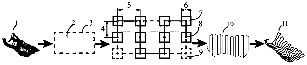
[0061] The skin defect model is a 20mm×15mm curved three-dimensional structure with a depth of 2mm. The in-situ printing process used is micro-extruded gelatin and sodium alginate, the line width of the extruded material is 1 mm, and the allowable error of the plane size boundary feature is 0.5 mm. The scanning equipment in the in situ printing system was used to obtain the three-dimensional point cloud surface of the two-layer skin defect with a depth of 1mm and 2mm, respectively, and the resolution of each layer of point cloud data was 0.2mm. Therefore, according to the method in the patent, the value range of the grid size parameter is 0.2-0.4mm, the value range of the grid spacing parameter is 0-0.4mm, the line spacing parameter is 1mm according to the material line width, and the boundary indentation parameter is 0.5mm, and other parameters can be taken as: grid center point thinning parameter is 2, multi-layer printing parameter is 2, nozzle lift parameter is 10mm. A be...


PUM


Abstract

The invention discloses a path planning method for a non-continuous grid division three-dimensional point cloud. According to the method, the three-dimensional point cloud serves as input, a three-dimensional printing path serves as output, the non-continuous grid division three-dimensional point cloud is adopted for path planning, the precision and the calculation amount of path planning are controlled through a plurality of parameters, the parameters comprise two types, namely basic parameters and related technology parameters, the basic parameters comprise grid dimension parameters and gridspacing parameters, and the related technology parameters comprise grid center point sparsification parameters, line spacing parameters, boundary shrinkage parameters, multi-layer printing parametersand nozzle lifting parameters. The method has the advantages that path planning is directly carried out through the three-dimensional point cloud, 3D modeling is not needed, a non-continuous grid canreduce the calculation amount on the premise that the precision is guaranteed, the problems of different printing technologies, point cloud cavities, orthogonal paths and the like are taken into consideration in the parameter setting process, and the method can be applied to the various printing technologies.

Description

technical field [0001] The invention belongs to the field of material repair and in-situ printing in 3D printing, and in particular relates to a path planning method for dividing a three-dimensional point cloud surface by a discontinuous grid. Background technique [0002] According to the shape and characteristics of the defective part of the component, 3D printing repair directly on the defective part is a fast and easy repair method, which is expected to simplify the processing process in part replacement, and in the rapid repair of biological tissue damage (also defined as the original bit printing) to improve repair or damage recovery speed. [0003] Path planning technology is widely used in many fields, such as robot autonomous movement, UAV obstacle avoidance, missile flight, daily GPS navigation, etc. Any problem that can be topologically planned as a point-line network can be considered as a path planning problem. In 3D printing technology, path planning is an im...

Claims


Application Information

Patent Timeline
Patent Type & Authority Patents(China)
IPC IPC(8): B29C64/386B33Y50/00
CPCB29C64/386B33Y50/00
Inventor 连芩李晓李涤尘何晓宁顾恒
Owner XI AN JIAOTONG UNIV
Why Eureka
Try Eureka