Labeling machine used for installing handle on PET container

A labeling machine and labeling technology, applied in the directions of labeling machines, labels, packaging, etc., can solve the problems of high additional energy consumption, complexity, and high additional investment cost space requirements, and achieve the effect of reducing investment costs and energy consumption.

Active Publication Date: 2016-11-16
KRONES AG
View PDF6 Cites 2 Cited by
  • Summary
  • Abstract
  • Description
  • Claims
  • Application Information

AI Technical Summary

Problems solved by technology

This means high additional investment costs and increased space requirements for the customer
In addition, these separate machines bring high additional energy consumption
Manufacturing handles or handles in stretch blow molding machines is a complex and cost-intensive process

Method used


Image

  • Labeling machine used for installing handle on PET container
  • Labeling machine used for installing handle on PET container
  • Labeling machine used for installing handle on PET container

Examples


Embodiment Construction

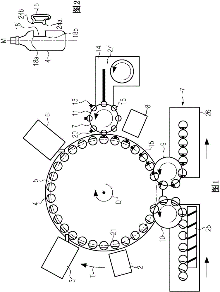
[0028] figure 1 An embodiment of a labeling machine according to the invention is shown. In this exemplary embodiment, the labeling machine is designed as a rotary labeling machine.

[0029] The labeling machine 1 here has a container infeed 10 in the form of an infeed star wheel, to which, for example, PET containers 4 , here bottles, are conveyed via a one-piece screw 25 . Furthermore, the labeling machine comprises a transport unit in the form of a turntable which, as indicated by the arrow, rotates about a central axis D in the transport direction T. The turntable has a plurality of rotating disks 21 arranged at equal distances on a common circle, on which PET containers are erected and held in a known manner. The turntable 5 also has a delivery star 9 via which the labeled PET containers equipped with handles 15 can be transported to a removal device 26 .

[0030] Finally, the labeling machine 1 has a first position detection device 2 which is able to detect the rotati...


PUM


Abstract

The present invention relates to a labeling machine for attaching handles to PET containers, in particular to a labeling machine for PET containers, the labeling machine has a container input, with a plurality of A transport unit of aligned rotating discs, a labeling unit and a container output, wherein a handle feeder for attaching handles to the containers is arranged on the periphery of the transport unit.

Description

technical field [0001] The invention according to the preambles of claims 1 and 15 relates to a labeling machine for labeling PET containers and a method for attaching handles to PET containers. Background technique [0002] To facilitate the handling of PET containers or PET bottles by the end consumer, handles or handles are mounted on some bottles. There are already several possibilities here: [0003] After closing via the closure, a separate machine is used to squeeze the handle and thus fix it on the bottle. [0004] It is also possible to blow the bottle using a special process whereby two curved depressions are formed in the bottle. After filling and labelling, the handle is snapped into the recess using a separate machine. [0005] Furthermore, there is the possibility that the handle or handle is inserted into the blow mold in the stretch blow molding machine before blowing. The container or bottle is then formed around the handle. [0006] All these known met...

Claims


Application Information

Patent Timeline
Patent Type & Authority Applications(China)
IPC IPC(8): B65D77/24
CPCB65C9/06B65B61/14B65C9/00B65D77/24
Inventor 阿诺·哈内尔罗伯特·奥斯特托马斯·菲利普
Owner KRONES AG
Why Eureka
Try Eureka