Anti-clogging spiral conveyer

A screw conveyor and anti-clogging technology, applied in the field of mechanical conveying, can solve the problems of slowing down of work efficiency, uneven feeding, clogging, etc., and achieve the effect of improving work efficiency and avoiding clogging

Inactive Publication Date: 2018-08-21
WUHU CHAOYUANLI IND DESIGN CO LTD
View PDF5 Cites 0 Cited by
  • Summary
  • Abstract
  • Description
  • Claims
  • Application Information

AI Technical Summary

Problems solved by technology

[0004] The purpose of the present invention is to provide an anti-clogging screw conveyor to solve the problem of uneven feeding of the original screw conveyor proposed in the above-mentioned background technology when it is in use, and the friction between the material and the groove wall during transportation. The high heat makes some materials with low melting point deform and agglomerate rapidly, forming a blockage, which not only slows down the working efficiency, but also causes the motor to be damaged due to overload operation.

Method used


Image

  • Anti-clogging spiral conveyer
  • Anti-clogging spiral conveyer
  • Anti-clogging spiral conveyer

Examples


Embodiment Construction

[0016] The following will clearly and completely describe the technical solutions in the embodiments of the present invention with reference to the accompanying drawings in the embodiments of the present invention. Obviously, the described embodiments are only some, not all, embodiments of the present invention. Based on the embodiments of the present invention, all other embodiments obtained by persons of ordinary skill in the art without making creative efforts belong to the protection scope of the present invention.

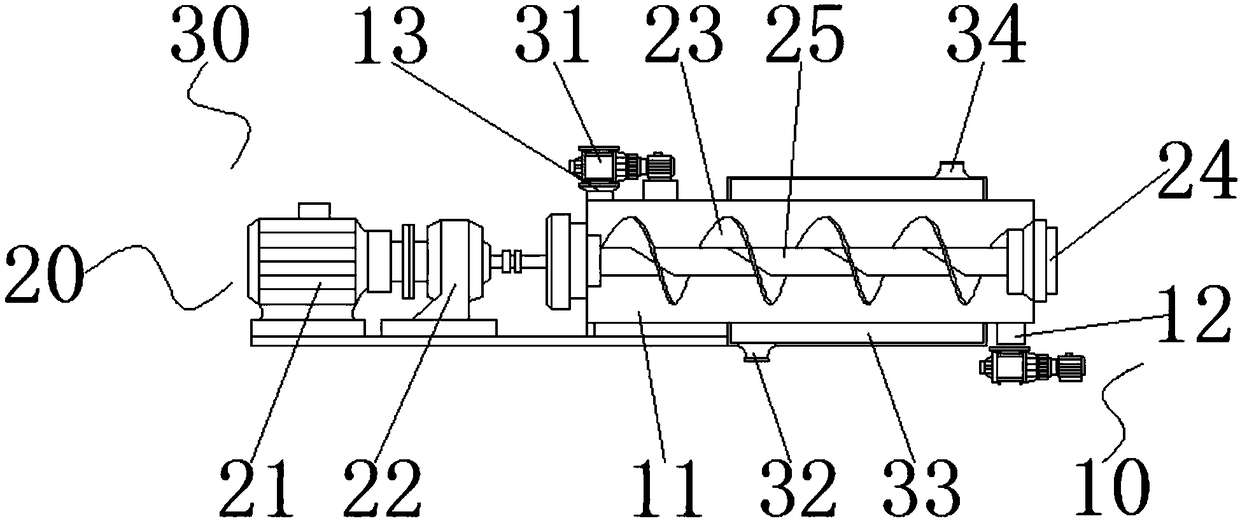
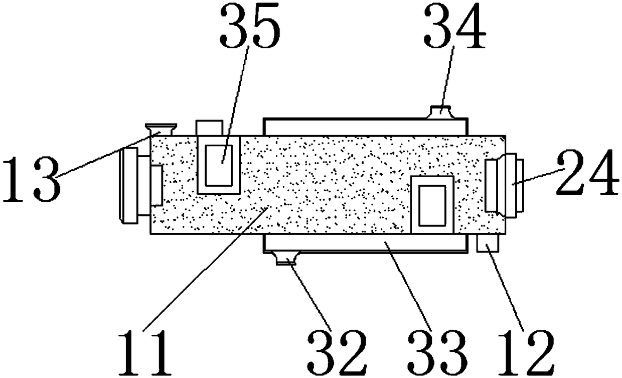
[0017] An anti-clogging screw conveyor, comprising a housing assembly 10, a drive assembly 20 and a cleaning assembly 30, the housing assembly 10 includes an outer frame 11, a material outlet 12 and a material inlet 13, and the top left end of the outer frame 11 is provided with a feeding Port 13, feed inlet 13 is welded with outer frame 11, and the bottom right end of outer frame 11 is provided with discharge port 12, and discharge port 12 is welded with outer...


PUM


Abstract

The invention discloses an anti-clogging spiral conveyer which comprises a shell component, a driving component and a cleaning component. The shell component comprises an outer frame, a discharging port and a feeding port, the feeding port is formed in the top left end of the outer frame and welded with the outer frame, and the discharging port is formed in the bottom right end of the outer frameand welded with the outer frame. An unloader is additionally arranged at the top of the feeding port, a switch of the unloader is turned on when the spiral conveyer works, an impeller rotates throughan impeller shaft by rotation of an electric motor, the space in the impeller can be filled with materials falling in from the upper portion at the moment, the materials uniformly fall to the feedingport along with rotation of the impeller, cold water is injected to a water inlet of a condenser pipe when the materials are low in melting point, the materials arrive in the condenser pipe on the outer side wall of the outer frame, tank wall temperature is rapidly reduced, clogging caused by deformation caking due to material friction heating is avoided, and the working efficiency of the spiral conveyer is improved.

Description

technical field [0001] The invention belongs to the technical field of mechanical transportation, and in particular relates to an anti-clogging screw conveyor. Background technique [0002] The screw conveyor is a kind of machine that uses the motor to drive the screw to rotate and push the material to achieve the purpose of conveying. It can be conveyed horizontally, inclined or vertically. It has a simple structure, small cross-sectional area, good sealing, convenient operation, easy maintenance, and convenient Closed transportation and other advantages. [0003] When the original screw conveyor is in use, due to the frequent occurrence of uneven feeding, coupled with the high heat generated by the friction between the material and the tank wall during transportation, some materials with low melting points are rapidly deformed and agglomerated, forming a blockage, which not only works The efficiency slows down, and the motor is damaged due to overload operation. Content...

Claims


Application Information

Patent Timeline
IPC IPC(8): B65G33/14B65G33/24B65G69/20
CPCB65G33/14B65G33/24B65G69/20
Inventor 王庆云刘超峰王伟祝荣
Owner WUHU CHAOYUANLI IND DESIGN CO LTD
Why Eureka
Try Eureka