
Cap suction and conveying mechanism for capper

A seaming machine and conveying mechanism technology, applied in the direction of flanged bottle caps, etc., can solve the problems of slow and discontinuous feeding of caps, and achieve the effect of continuous feeding of caps

Inactive Publication Date: 2018-08-21
舟山威尔曼机械科技有限公司
View PDF7 Cites 3 Cited by
  • Summary
  • Abstract
  • Description
  • Claims
  • Application Information

AI Technical Summary

Problems solved by technology

[0003] In order to solve the problem of slow and discontinuous delivery of the existing cover delivery device, the present invention provides a suction cover and cover delivery mechanism on the seaming machine

Method used


Image

  • Cap suction and conveying mechanism for capper
  • Cap suction and conveying mechanism for capper
  • Cap suction and conveying mechanism for capper

Examples


Embodiment Construction

[0024] Below in conjunction with accompanying drawing and embodiment the present invention will be further described:

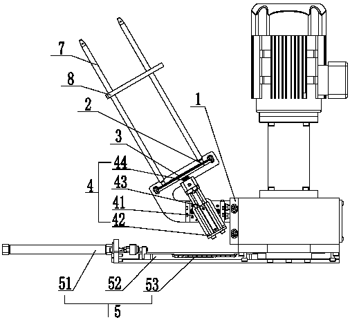
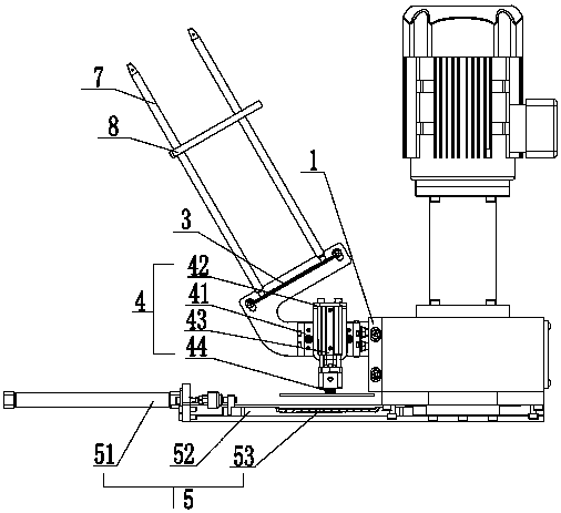
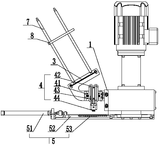
[0025] In the example, such as figure 1 , figure 2 , image 3 , Figure 4 , Figure 5 As shown, the cap suction and cap delivery mechanism on the seaming machine includes a frame 1, and the frame 1 is provided with a placement rack 2 for placing bottle caps, and the bottom of the placement rack 2 is provided with a stopper for preventing bottle caps from falling. Part 3, the bottom of the placement frame 2 is provided with a rotary conveying mechanism 4, the rotary conveying mechanism 4 has a No. 1 position for fixing the bottle cap, a No. 2 position for rotating and conveying the bottle cap, and a third position for releasing the bottle cap. Below the rotary conveying mechanism 4 is provided a conveying mechanism 5 for conveying the bottle caps to the sealing station. The rotary conveying mechanism 4 first fixes the bottle cap at the bottom of the shel...


PUM


Abstract

The invention discloses a cap suction and conveying mechanism for a capper, which solves the problems of low cap conveying speed and incontinuity existing in conventional cap conveyers. The cap suction and conveying mechanism is characterized by comprising a frame, wherein a holder for the placement of bottle caps is arranged on the frame, a retainer for preventing cap dropping is arranged on thebottom of the holder, a rotating conveying mechanism is arranged under the holder, the rotating conveying mechanism is provided with a first position for fixing a cap, a second position for rotatablyconveying the cap, and a third position for releasing the cap, and a conveying mechanism for conveying the cap to a capping station is arranged under the rotating conveying mechanism. The rotating conveying mechanism of the cap suction and conveying mechanism first fixes one cap on the bottom of the holder, then pulls out the cap from the bottom of the holder and rotatably conveys the cap to be over the conveying mechanism, the rotating conveying mechanism is restored after releasing the cap, the cap drops into the conveying mechanism, and finally, the conveying mechanism conveys the cap to the capping station. The caps can be quickly and continuously conveyed.

Description

technical field [0001] The invention relates to the technical field of can seaming machines, in particular to a suction cap and cap feeding mechanism on the can seaming machine. Background technique [0002] At present, due to the convenience of use and portability of bottle filling products, capping machines are widely used in daily chemical, food, medical and other industries. Traditional capping devices require manual feeding, but capping machines They are all mass-produced and processed. If the tank body of the capping machine is manually installed, not only the production efficiency will be low, but also the processing cost will be increased, and there will be safety hazards. A slight improper operation may cause personal injury; The cap feeding device is used for mechanical cap feeding, but the existing cap feeding device has the problem that the cap feeding speed is slow and not continuous enough. Contents of the invention [0003] In order to solve the problem of ...

Claims


Application Information

Patent Timeline
Patent Type & Authority Applications(China)
IPC IPC(8): B67B3/06
Inventor 叶晓安谢作周
Owner 舟山威尔曼机械科技有限公司
Learn More