Unlock instant, AI-driven research and patent intelligence for your innovation.

Oil-water separation device for oily wastewater in chemical fiber production

An oil-water separation device and oil pollution technology, applied in the direction of grease/oily substance/suspton removal device, liquid separation, separation method, etc., can solve the problems of affecting the oil removal rate, high cost of wastewater treatment, and incomplete oil-water separation, etc., to achieve The effect of improving the oil yield and thoroughly separating oil and water

Inactive Publication Date: 2018-08-21
ZHEJIANG HUATESI POLYMER TECHN
View PDF1 Cites 2 Cited by
  • Summary
  • Abstract
  • Description
  • Claims
  • Application Information

AI Technical Summary

Problems solved by technology

[0002] In the process of chemical fiber production, oily wastewater will inevitably be produced. For environmental protection and recycling of wastewater after purification, oily wastewater must be treated. Traditional wastewater treatment costs are high, occupy a large area, and oil-water separation is not complete, and external power is required. accomplish
For example, the application number is CN201420346642.2, which is an oil-water separation device for oily waste water from chemical fiber production, including a primary water tank and a secondary water tank. The primary water tank is provided with a water inlet, and the top of the secondary water tank is provided with a water outlet. The primary water tank and The secondary water tank is connected through the oil-water separation enhancement device. Although the device strengthens the separation of oil and water and has low operating costs, but in the process of use, because the water level in the water tank cannot be kept constant, the floating oil collection pipe cannot be connected to the water surface in some cases. Contact with the slick oil, resulting in incomplete oil-water separation, affecting the oil removal rate and reducing the practicability of the device

Method used


Image

  • Oil-water separation device for oily wastewater in chemical fiber production
  • Oil-water separation device for oily wastewater in chemical fiber production
  • Oil-water separation device for oily wastewater in chemical fiber production

Examples


Embodiment Construction

[0015] The following will clearly and completely describe the technical solutions in the embodiments of the present invention with reference to the accompanying drawings in the embodiments of the present invention. Obviously, the described embodiments are only some, not all, embodiments of the present invention. Based on the embodiments of the present invention, all other embodiments obtained by persons of ordinary skill in the art without making creative efforts belong to the protection scope of the present invention.

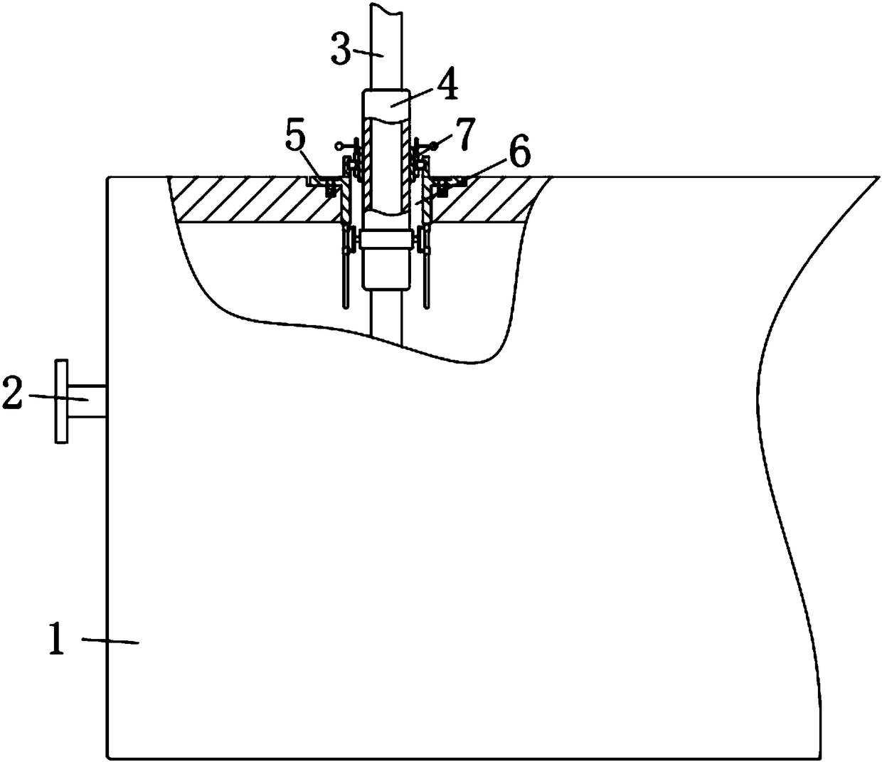
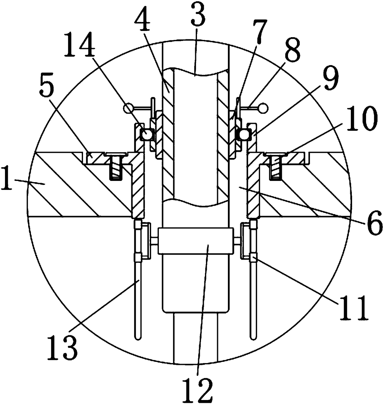
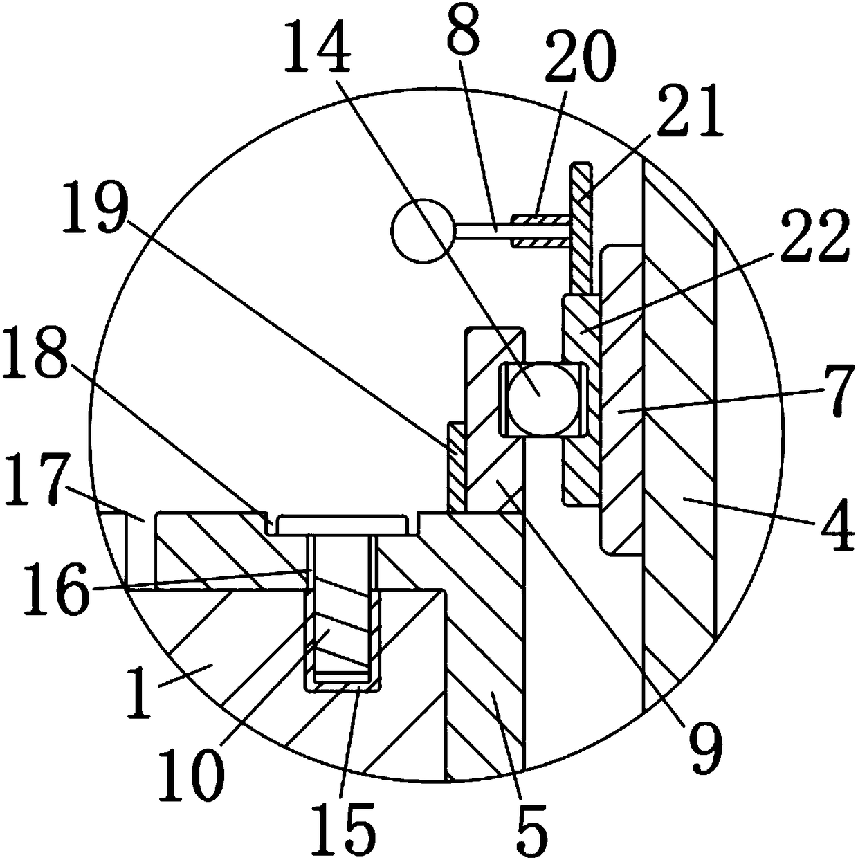
[0016] see Figure 1-4 , the present invention provides a technical solution: an oil-water separation device for oily waste water produced by chemical fiber, comprising a water tank 1, a water inlet 2 is provided on the outer wall of the left end of the water tank 1, the water inlet 2 communicates with the water tank 1, and the center of the upper outer wall of the water tank 1 is provided There is a through hole 6, and the oil slick collecting pipe 3 is arran...


PUM


Abstract

The invention discloses an oil-water separation device for oily wastewater in chemical fiber production. The oil-water separation device comprises a water tank, wherein a water inlet is formed in an outer wall at a left end of the water tank; the water inlet is communicated with the water tank; a through hole is formed in the outer wall at an upper end of the water tank; a floating oil collectingpipe is arranged in the through hole; the outer wall of the floating oil collecting pipe is in interference fit with an external threaded cylinder; the outer wall on an upper side of the external threaded cylinder is in threaded connection with an inner wall of an internal threaded cylinder; the outer wall of the internal threaded cylinder is fixedly connected with an inner cylinder. The oil-waterseparation device for oily wastewater in chemical fiber production keeps the external threaded cylinder and the floating oil collecting pipe from rotating by screwing a handle and limiting the external threaded cylinder and the floating oil collecting pipe through an external force, so that the external threaded cylinder and the floating oil collecting pipe move vertically; a lower end of the floating oil collecting pipe is always in contact with floating oil on a water surface by simple adjustment, so as to effectively realize more thorough oil-water separation in the water tank and improvethe yield of oil and the practicability of the device.

Description

technical field [0001] The invention relates to the technical field of chemical fiber production wastewater treatment, in particular to an oil-water separation device for chemical fiber production oily wastewater. Background technique [0002] In the process of chemical fiber production, oily wastewater will inevitably be produced. For environmental protection and recycling of wastewater after purification, oily wastewater must be treated. Traditional wastewater treatment costs are high, occupy a large area, and oil-water separation is not complete, and external power is required. accomplish. For example, the application number is CN201420346642.2, which is an oil-water separation device for oily waste water from chemical fiber production, including a primary water tank and a secondary water tank. The primary water tank is provided with a water inlet, and the top of the secondary water tank is provided with a water outlet. The primary water tank and The secondary water tank...

Claims


Application Information

Patent Timeline
Patent Type & Authority Applications(China)
IPC IPC(8): C02F1/40C02F103/38
CPCC02F1/40C02F2103/38C02F2201/002
Inventor 朱林军
Owner ZHEJIANG HUATESI POLYMER TECHN