Flow-mixing type rotating wheel capable of preventing blockages

A mixed-flow runner technology, applied in the field of water turbines, can solve the problem that the mixed-flow runner is easily blocked by foreign matter, so as to avoid poor water flow, increase power generation efficiency, and improve the effect of crushing

Active Publication Date: 2018-08-21
SICHUAN HAOYUAN ELECTROMECHANICAL CO LTD
View PDF5 Cites 3 Cited by
  • Summary
  • Abstract
  • Description
  • Claims
  • Application Information

AI Technical Summary

Problems solved by technology

[0006] The invention overcomes the deficiencies of the prior art, provides a mixed-flow runner that can avoid clogging, and solves the problem that the mixed-flow runner of the existing hydraulic turbine is easily blocked by foreign matter

Method used


Image

  • Flow-mixing type rotating wheel capable of preventing blockages
  • Flow-mixing type rotating wheel capable of preventing blockages

Examples


Embodiment 1

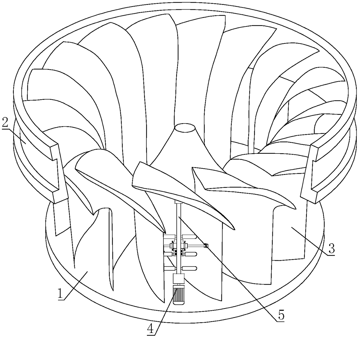
[0027] A mixed-flow runner for preventing clogging, comprising an upper crown 1 and a lower ring 2, a number of mixed-flow blades 3 are connected between the upper crown 1 and the lower ring 2; a driving mechanism 4 is arranged between adjacent mixed-flow blades 3, and the driving The mechanism 4 is installed on the upper crown 1, the output end of the driving mechanism 4 is connected to the rotating shaft 5, and the other end of the rotating shaft 5 is connected to the mixed-flow blade 3 through a bearing, and the rotating shaft 5 is connected to be used for crushing debris between adjacent mixed-flow blades 3 Fragmentation device.

[0028] The driving mechanism 4 of the present invention can drive the rotating shaft 5 to rotate, and the disintegrating device on the rotating shaft 5 can disintegrate the clogged sundries to prevent the sundries from clogging the area between the adjacent mixing blades 3 . After the disintegration device cleans the Francis runner, the water flo...

Embodiment 2

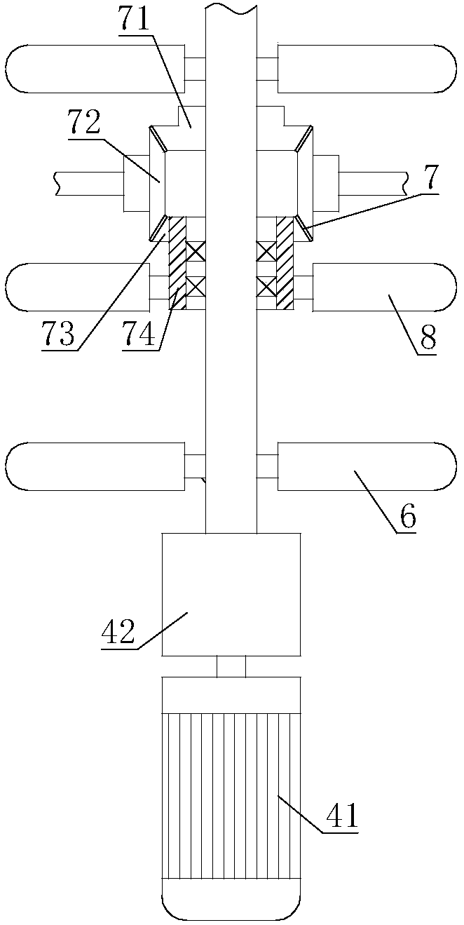
[0030] On the basis of Embodiment 1, the crushing device includes a forward crushing paddle 6 and a reversing mechanism 7, and the forward crushing paddle 6 and the reversing mechanism 7 are all connected to the rotating shaft 5, and the reversing mechanism 7 Connected with reverse crushing paddle 8.

[0031] After being reversed by the reversing mechanism 7, the rotation direction of the reverse crushing paddle 8 is opposite to the rotation direction of the forward crushing paddle 6. The forward disintegrating blade 6 and the reverse disintegrating blade 8 can disintegrate and clean up the debris from two directions, avoiding the situation that the debris cannot be completely disintegrated when the disintegrating blade rotates in one direction , improve the effect of debris crushing, and ensure the smooth and efficient work of the Francis runner.

Embodiment 3

[0033] On the basis of Embodiment 1 or Embodiment 2, the reversing mechanism 7 includes a driving bevel gear 71, the driving bevel gear 71 is meshed with a driving bevel gear 72, and the central shaft of the driving bevel gear 72 is connected to the mixing blade 3 through a bearing , the driving bevel gear 72 meshes with a driven bevel gear 73; the rotating shaft 5 is connected with a sleeve 74 through the middle bearing, and the driven bevel gear 74 and the reverse disintegration paddle 8 are all fixedly installed on the sleeve 74.

[0034] When the rotating shaft 5 rotates, the driving bevel gear 71 rotates with the rotating shaft 5. After the transmission of the driving bevel gear 72, the direction of rotation of the driven bevel gear 73 is opposite to that of the driving bevel gear 71, and the reverse crushing paddle on the casing 74 The rotation direction of the blade 8 is opposite to the rotation direction of the forward disintegration paddle 6, which realizes the effect ...


PUM


Abstract

The invention relates to the field of water turbines, in particular to a flow-mixing type rotating wheel capable of preventing blockages. According to the technical scheme, the flow-mixing type rotating wheel capable of preventing the blockages comprises an upper crown, a lower ring and a plurality of flow-mixing blades, wherein the plurality of flow-mixing blades are connected between the upper crown and the lower ring; a driving mechanism is arranged between every two adjacent flow-mixing blades, the driving mechanisms are arranged on the upper crown, the output ends of the driving mechanisms are connected to rotating shafts, and the other ends of the rotating shafts are connected to the flow-mixing blades through bearings, and the rotating shafts are connected to crushing devices used for crushing sundries between adjacent flow-mixing blades. According to the flow-mixing type rotating wheel, the blockages are prevented, and the problem that the flow-mixing type rotating wheel of anexisting water turbine is prone to being blocked by foreign matters is solved.

Description

technical field [0001] The invention relates to the field of water turbines, in particular to a mixed-flow runner for preventing blockage. Background technique [0002] The Francis turbine, also known as the Francis turbine, is a type of impact turbine, invented by the American engineer Francis in 1849, also known as the Francis turbine, or the radial flow turbine. The water flows radially into the runner from all around, and then flows out of the runner approximately axially. The runner is composed of an upper crown, a lower ring and blades. The development trend in recent years is high water head, large capacity, high specific speed and high efficiency. [0003] The runner is directly connected to the main shaft and is the rotating part of this type of turbine. The runner is composed of an upper crown, a lower ring, a discharge cone and a number of fixed blades. Its shape and matching dimensions of each component vary according to the water head used. different. [0004...

Claims


Application Information

Patent Timeline
Patent Type & Authority Applications(China)
IPC IPC(8): F03B3/02F03B3/12F03B11/08
CPCF03B3/02F03B3/125F03B11/08F05B2260/63Y02E10/20
Inventor 欧丁明
Owner SICHUAN HAOYUAN ELECTROMECHANICAL CO LTD
Why Eureka
Try Eureka