Rotor compressor and heat exchange equipment comprising same

A rotor compressor and crankshaft technology, applied in the field of rotor compressors, can solve problems such as insufficient lubrication of the crankshaft and support structure, and achieve the effects of improving user experience, reducing vibration and noise, and improving work performance

Pending Publication Date: 2018-08-21
ZHUHAI GREE REFRIGERATION TECH CENT OF ENERGY SAVING & ENVIRONMENTAL PROTECTION
View PDF4 Cites 2 Cited by
  • Summary
  • Abstract
  • Description
  • Claims
  • Application Information

AI Technical Summary

Problems solved by technology

[0004] The main purpose of the present invention is to provide a rotary compressor and its heat exchange equipment to solve the problem of insufficient lubrication between the crankshaft and the supporting structure of the rotary compressor in the prior art

Method used


Image

  • Rotor compressor and heat exchange equipment comprising same
  • Rotor compressor and heat exchange equipment comprising same
  • Rotor compressor and heat exchange equipment comprising same

Examples


Embodiment 1

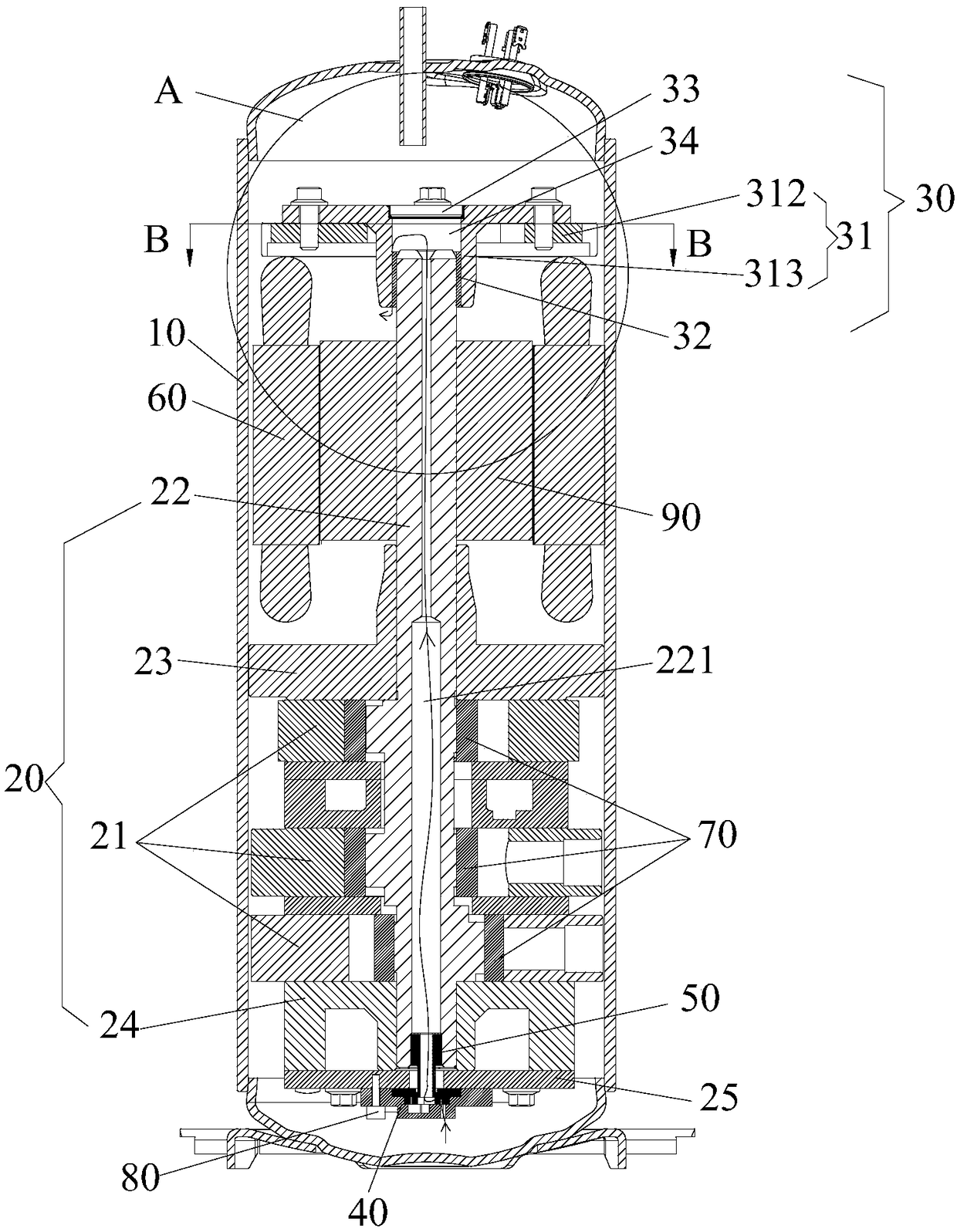
[0039] Such as figure 1 As shown, the rotary compressor includes a crankshaft 22, a support structure 30, and a power structure 40. The crankshaft 22 has an oil through hole 221 extending along its axial direction. The support structure 30 supports the crankshaft 22 to prevent the crankshaft 22 from moving in its radial direction. The power structure 40 transports the lubricating medium in the oil pool to between the crankshaft 22 and the support structure 30 through the oil through hole 221.

[0040] Applying the technical solution of this embodiment, the support structure 30 is used to support the upper end of the crankshaft 22 to prevent the crankshaft 22 from swinging during operation. During the operation of the rotary compressor, the power structure 40 transports the lubricating medium in the oil sump between the crankshaft 22 and the support structure 30 through the oil through hole 221 provided on the crankshaft 22, so as to carry out the connection between the support s...

Embodiment 2

[0073] The difference between the rotor compressor in the second embodiment and the first embodiment is that the type of the bearing structure 32 is different.

[0074] Such as Figure 8 As shown, the bearing structure 32 is a rolling bearing. Specifically, the inner ring of the bearing structure 32 is in clearance fit with the crankshaft 22, and the outer ring of the bearing structure 32 is fixed in the central through hole 311 of the support assembly 31 to support and limit the upper end of the crankshaft 22.

[0075] From the above description, it can be seen that the above-mentioned embodiments of the present invention achieve the following technical effects:

[0076] The support structure is used to support the upper end of the crankshaft to prevent the crankshaft from swinging during operation. During the operation of the rotary compressor, the power structure transports the lubricating medium in the oil sump to the crankshaft and the support structure through the oil through...


PUM


Abstract

The invention provides a rotor compressor and heat exchange equipment comprising the same. The rotor compressor comprises a crankshaft, a supporting structure and a power structure, wherein the crankshaft is provided with an oil supply hole extending in the axial direction of the crankshaft; the supporting structure is used for supporting the crankshaft so as to prevent the crankshaft from movingin the radial direction of the supporting structure; the power structure is used for delivering a lubrication medium in an oil sump to the place between the crankshaft and the supporting structure through the oil supply hole. Through the rotor compressor, the problem that a crankshaft of a rotor compressor and a supporting structure are lubricated insufficiently in the prior art is solved effectively.

Description

Technical field [0001] The present invention relates to the technical field of rotor compressors, in particular to a rotor compressor and a heat exchange device having the same. Background technique [0002] At present, in order to improve the refrigeration capacity of the rotary compressor and increase its refrigeration capacity, multiple cylinders are usually used to operate together. However, the arrangement of multiple cylinders in the rotary compressor causes the length of the rotating shaft to increase, and the distance between the upper and lower flanges increases. At the same time, the rotor of the motor also needs to be heightened, which leads to an increase in the deflection of the rotor. The phenomenon that the rotor contacts the stator during high-speed operation is likely to occur, which increases the noise and vibration of the rotor compressor and reduces the reliability of the rotor compressor. Sex. [0003] In the prior art, in order to prevent the above phenomeno...

Claims


Application Information

Patent Timeline
Patent Type & Authority Applications(China)
IPC IPC(8): F04C29/02
CPCF04C29/025
Inventor 阙沛祯魏会军杨欧翔胡艳军翟元彬向柳苗旺
Owner ZHUHAI GREE REFRIGERATION TECH CENT OF ENERGY SAVING & ENVIRONMENTAL PROTECTION
Why Eureka
Try Eureka