Supercharge Your Innovation With Domain-Expert AI Agents!

Multistage damping engine pull rod

An engine, stage damping technology, applied in the direction of shock absorber, spring/shock absorber, shock absorber, etc., can solve the problems of inability to guarantee the working state of the engine, inconvenient installation of the engine rod, affecting the normal use of the engine, etc. Easy installation, easy maintenance and disassembly, long service life effect

Pending Publication Date: 2018-08-21
南京世界村汽车动力有限公司
View PDF0 Cites 1 Cited by
  • Summary
  • Abstract
  • Description
  • Claims
  • Application Information

AI Technical Summary

Problems solved by technology

[0002] In the automobile manufacturing industry, for a long time, people have been trying to reduce the unnecessary vibration of the engine, so as to reduce the additional power consumed by the engine due to the vibration. Generally speaking, there are active and passive methods to reduce the excessive vibration of the engine. The tie rod belongs to the latter, which is used to suppress the excessive shaking of the engine, so that the engine power can be practically transmitted to the transmission, and reduce the loss of power during rapid acceleration. Guarantee the working condition of the engine, and the existing engine tie rods will be vibrated during use, which will be easily damaged, affecting the normal use of the engine, and even causing serious consequences. At the same time, the existing engine tie rods are inconvenient to install, not easy to replace and repair, Therefore, the present invention proposes a multistage damping engine tie rod to solve the problems existing in the prior art

Method used


Image

  • Multistage damping engine pull rod
  • Multistage damping engine pull rod
  • Multistage damping engine pull rod

Examples


Embodiment Construction

[0016] In order to deepen the understanding of the present invention, the present invention will be further described below in conjunction with the examples, which are only used to explain the present invention, and do not constitute a limitation to the protection scope of the present invention.

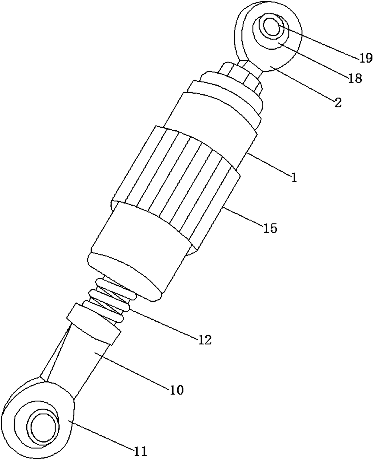
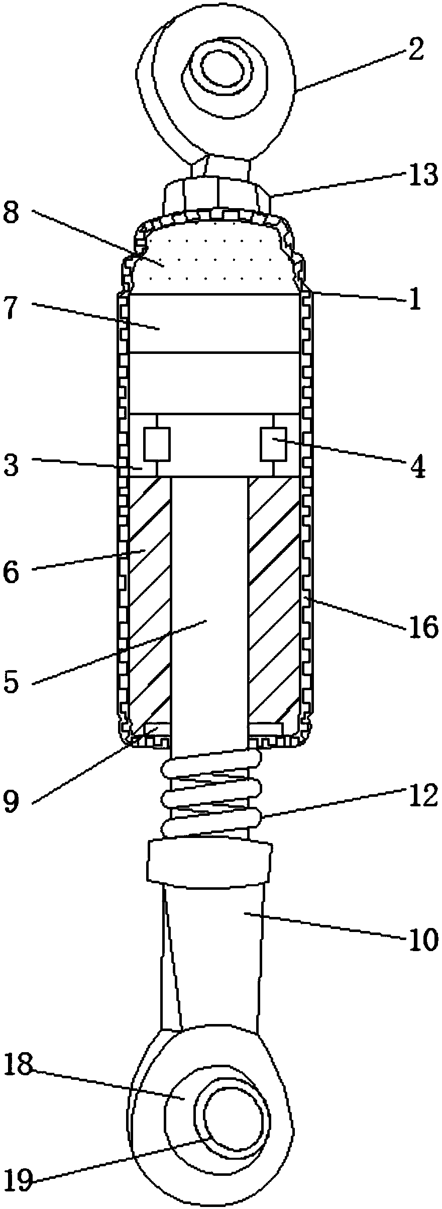
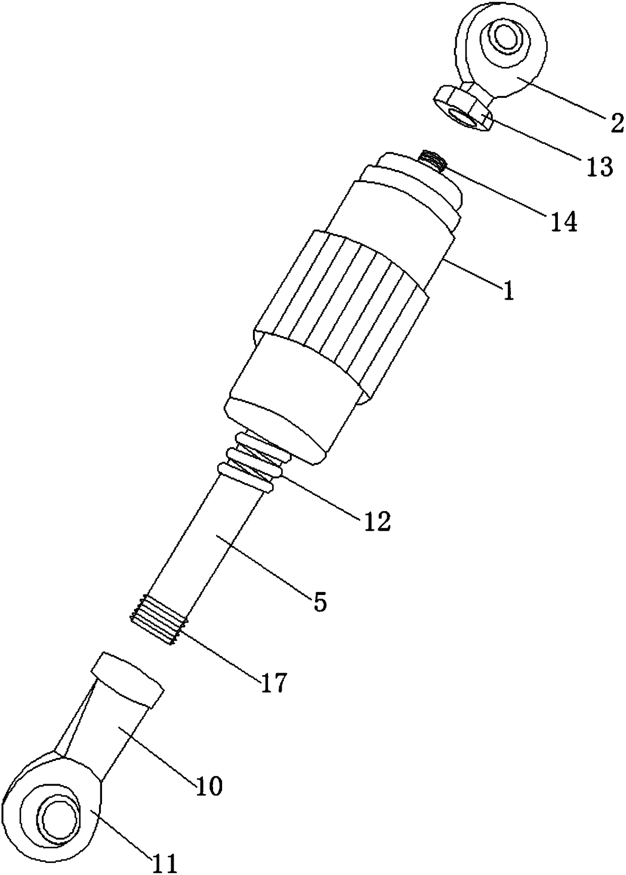
[0017] according to figure 1 , 2 , 3, the present embodiment provides a multi-stage shock-absorbing engine pull rod, including a main body 1, a main pull head 2, a piston 3, a valve 4 and a piston rod 5, and the top of the main body 1 is equipped with a main pull Head 2, a piston 3 is provided at the middle position in the main pipe body 1, and two sets of valves 4 are arranged on the piston 3, and a piston rod 5 extending to the outside of the main pipe body 1 is provided at the middle position of the bottom of the piston 3 , and the inside of the main body 1 on the outside of the piston rod 5 is provided with damping oil 6, the top inside the main body 1 is provided with a split p...


PUM


Abstract

The invention discloses a multistage damping engine pull rod. The pull rod comprises a main pipe body, a main pull head, a piston, valves and a piston rod, wherein the main pull head is installed at the top of the main pipe body, a middle position inside the main pipe body is provided with the piston on which two sets of valves are arranged, a middle position at the bottom of the piston is provided with a piston rod which stretches out of the main pipe body, damping oil is arranged inside the main pipe body on an outer side of the piston rod, the top inside the main pipe body is provided witha division piston, nitrogen gas is arranged between the division piston and a top wall in the main pipe body, and a seal ring is arranged around an outer side of the piston rod and located at the bottom of an inner side of the main pipe body. According to the multistage damping pull rod for the engine, the friction of the damping oil inside the main pipe body can be utilized to inhibit an engine from shaking excessively, structures inside the main pull head and a sub-pull head can be utilized to disperse transmitted vibration, a spring at the bottom of the main pipe body can further be utilized to play a part in buffering, and the multistage damping has a better effect, so as to ensure that the engine can normally operate.

Description

technical field [0001] The invention relates to the technical field of auto parts, in particular to a multi-stage damping engine tie rod. Background technique [0002] In the automobile manufacturing industry, people have been trying to reduce the unnecessary vibration of the engine so as to reduce the extra power consumed by the engine due to the vibration. Generally speaking, there are active and passive methods to reduce the excessive vibration of the engine. The tie rod belongs to the latter, which is used to suppress the excessive shaking of the engine, so that the engine power can be practically transmitted to the transmission, and reduce the loss of power during rapid acceleration. Guarantee the working condition of the engine, and the existing engine tie rods will be vibrated during use, which is easily damaged, affecting the normal use of the engine, and even causing serious consequences. At the same time, the existing engine tie rods are inconvenient to install, no...

Claims


Application Information

Patent Timeline
Patent Type & Authority Applications(China)
IPC IPC(8): F16F13/00F16F9/10F16F9/32F16F9/42F16F9/54B60K5/12
CPCF16F9/103F16F9/3235F16F9/42F16F9/54F16F13/007B60K5/1208
Inventor 孙兰娟李健
Owner 南京世界村汽车动力有限公司
Features
  • R&D
  • Intellectual Property
  • Life Sciences
  • Materials
  • Tech Scout
  • Unparalleled Data Quality
  • Higher Quality Content
  • 60% Fewer Hallucinations
Learn More