Device for improving reliability of high voltage direct current relay

A high-voltage direct current and relay technology, applied in the direction of relays, electromagnetic relays, detailed information of electromagnetic relays, etc., can solve the problems of increasing arcing time, increasing the possibility of bouncing, and being volatile, so as to reduce arcing time and suppress bouncing time , the effect of improving reliability

Pending Publication Date: 2018-08-21
TSE TECH NINGBO
View PDF2 Cites 0 Cited by
  • Summary
  • Abstract
  • Description
  • Claims
  • Application Information

AI Technical Summary

Problems solved by technology

Therefore, in order to solve the problem of high-voltage and high-current loads, relays generally adopt the form of ceramic packaging and magnetic blowout arc extinguishing. However, in the arc extinguishing chamber, some plastic insulators are commonly used to isolate the large current and the relay body. The purpose is to connect The electromagnet body and the moving contact, such as Panasonic AEV14024, and the plastic is easy to volatilize a variety of organic substances as the temperature rises in the relay interrupter, which adheres to the contact surface and makes the contact invalid
[0003] Existing insulator structures such as CN106486323 or CN107622917 adopt a "bow" structure, which is large in size, which is not conducive to the miniaturization and lightweight requirements of on-board relays
In addition, most relays on the market use buffer springs to reduce the impact between contacts, but this increases the possibility of bouncing and increases the arcing time, which is not conducive to the life of the contacts.

Method used


Image

  • Device for improving reliability of high voltage direct current relay
  • Device for improving reliability of high voltage direct current relay
  • Device for improving reliability of high voltage direct current relay

Examples


Embodiment Construction

[0017] Below in conjunction with specific embodiment, further illustrate the present invention. It should be understood that these examples are only used to illustrate the present invention and are not intended to limit the scope of the present invention. In addition, it should be understood that after reading the teachings of the present invention, those skilled in the art can make various changes or modifications to the present invention, and these equivalent forms also fall within the scope defined by the appended claims of the present application.

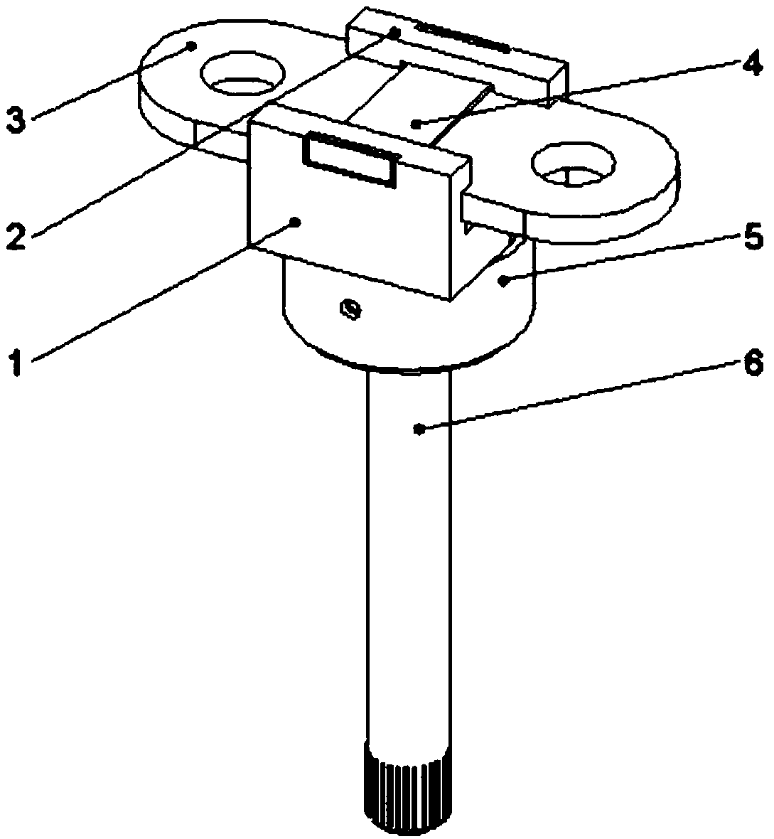
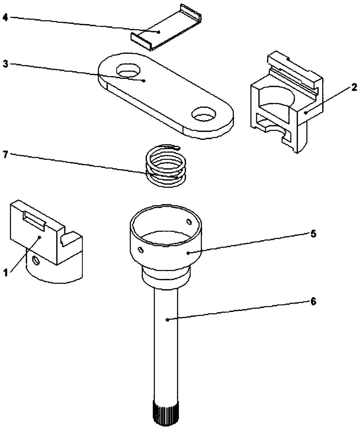
[0018] Embodiments of the present invention relate to a device for improving the reliability of high-voltage DC relays, such as Figure 1-Figure 3 As shown, it includes a left insulator 1, a right insulator 2 and a bridge 3. The left insulator 1 and the right insulator 2 are combined to form an insulator body. The upper part of the insulator body is a concave structure, and the lower part is a cylindrical structure; The lower ...


PUM


Abstract

The invention relates to a device for improving the reliability of a high voltage direct current relay. The device comprises a left insulator, a right insulator and slab bridges, the left insulator and the right insulator are joined together to form an insulator body, the upper portion of the insulator body is of a structure shaped like the Chinese character 'ao', and the lower portion is of a cylindrical structure; the lower portion of the inside of the cylindrical structure forms a first cavity, the upper portion forms a second cavity, and the first cavity and the second cavity are isolatedfrom each other; grooves are formed in the inner sides of the two sidewalls protruding from the structure shaped like the Chinese character 'ao'; the first cavity is used for being connected with a boss of a guide rod, and the second cavity is connected with a buffer spring; the slab bridges are placed in the grooves. The device can effectively solve the high current of the high voltage direct current relay slab bridges and the insulation of an electromagnet portion.

Description

technical field [0001] The invention relates to the technical field of high voltage direct current relays, in particular to a device for improving the reliability of high voltage direct current relays. Background technique [0002] With the development of new energy vehicles, the requirements for high-voltage DC relays are becoming more and more stringent, and the load capacity of the relays has also increased from 40A to 120A or even 600A in the future, and the instantaneous surge caused by different loads is even more rated Several times or even 20 times the load current. Therefore, in order to solve the problem of high-voltage and high-current loads, relays generally adopt the form of ceramic packaging and magnetic blowout arc extinguishing. However, in the arc extinguishing chamber, some plastic insulators are commonly used to isolate the large current and the relay body. The purpose is to connect The electromagnet body and the moving contact, such as Panasonic AEV14024...

Claims


Application Information

Patent Timeline
Patent Type & Authority Applications(China)
IPC IPC(8): H01H50/02
CPCH01H50/026H01H2050/028
Inventor 吴国华
Owner TSE TECH NINGBO
Why Eureka
Try Eureka