Wedge drive

A driving device, wedge-type technology, applied in the directions of punching machines, presses, manufacturing tools, etc., can solve the problems of lack, complex and expensive manufacturing of wedge-type driving devices, high cost, etc., and achieve the effect of easy construction

Inactive Publication Date: 2018-08-21
哈拉尔德·魏格尔特
View PDF9 Cites 0 Cited by
  • Summary
  • Abstract
  • Description
  • Claims
  • Application Information

AI Technical Summary

Problems solved by technology

However, the production of this type of wedge drive is very complicated and expensive due to the inclined guide surfaces of the guide
In order to reduce the expenditure and costs in the manufacture of the wedge drive, it has been proved impossible to cancel the correspondingly inclined guide surface in the prior art, beca

Method used


Image

  • Wedge drive
  • Wedge drive
  • Wedge drive

Examples


Embodiment Construction

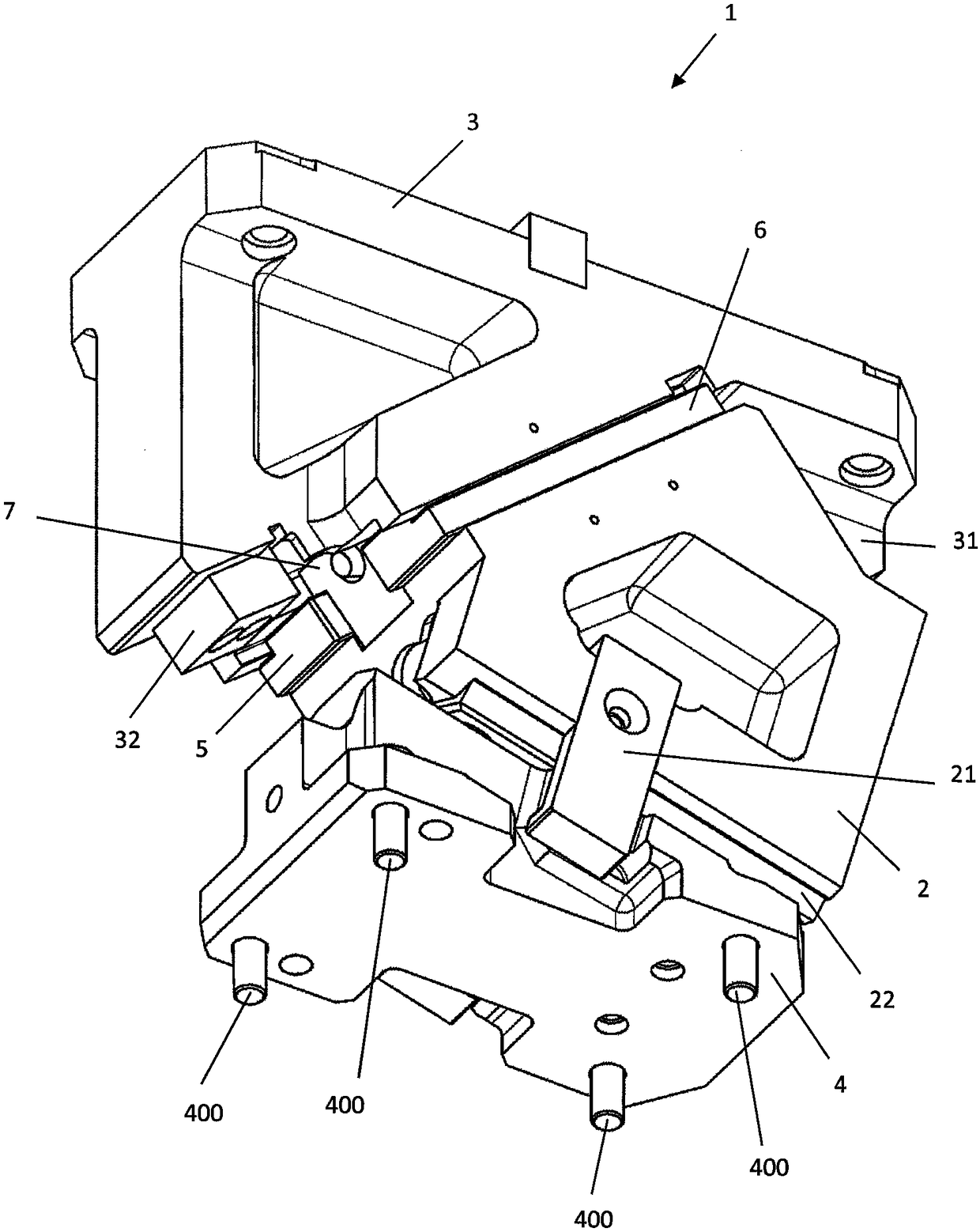
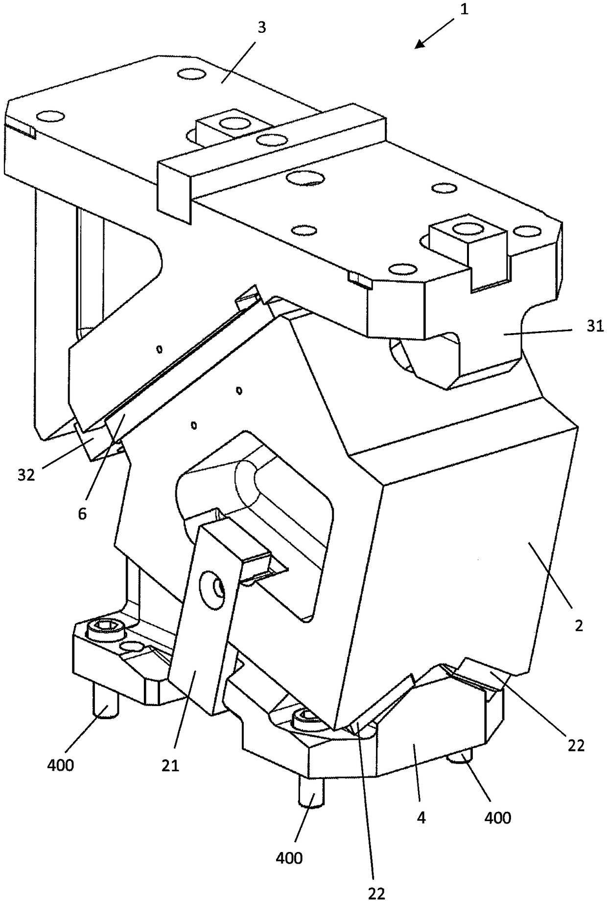
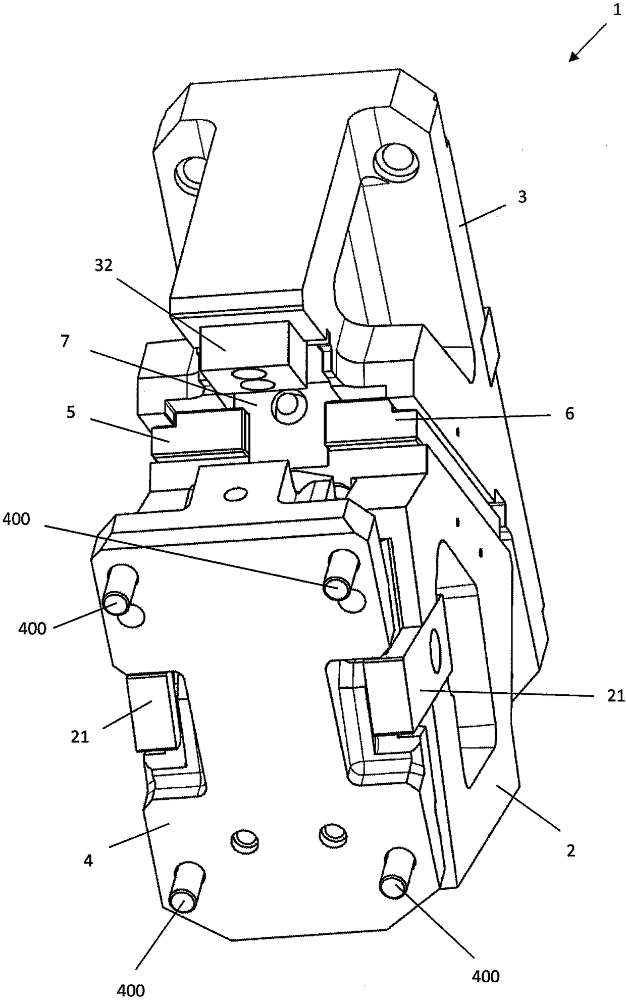
[0038] Include Figure 1a 1, 1b and 1c schematically show an embodiment of a wedge drive 1 according to the invention viewed from different perspectives in different schematic diagrams. As can be seen from FIG. 1 , the wedge drive according to the invention comprises a sliding element 2 which is arranged vertically between a sliding element receiver 3 and a drive element 4 . The sliding element 2 is connected via a guide to a sliding element receiving device 3, which here comprises a slide assembly consisting of three slides, a middle slide 7 and two side slides 5, 6. Furthermore, the sliding element 2 is connected to the drive element 4 via a drive guide, which comprises a sliding slide 22 which is arranged on the side of the sliding element 2 facing the drive element 4 . Furthermore, the sliding element 2 is connected to the drive element 4 via a return stroke 21, by means of which it is ensured that the sliding element 2 also remains connected to the drive element 4 durin...


PUM


Abstract

The invention relates to a wedge drive (1) for redirecting a vertical press force into a horizontal, linear working motion, the wedge drive (1) comprising a slide element (2), a driving element (4), and a slide-element holder (3), wherein the slide element (2) is arranged vertically between the driving element (4) and the slide-element holder (3), wherein the slide element (2) and the slide-element holder (3) are designed as two guide elements (2, 3), on which a sliding plate formation (5, 6, 7) is arranged, wherein the sliding plate formation is comprised by a guide device, which is designedto linearly guide the slide element (2) along the slide-element holder (3) in a sliding direction (X).

Description

technical field [0001] The invention relates to a wedge drive according to the preamble of claim 1 for guiding large vertical pressure forces, in particular exceeding 100 kN, into a horizontal linear working movement. Background technique [0002] Wedge drives of this type are mostly used in forming processes in which the material has to be deformed with very high force expenditure and with very high precision. The main field of application of the wedge drive is the automotive industry. For example, wedge drives are used here for the production of body parts, in particular for the processing of large sheet metal parts, for example cutting, drilling or deformation of the sheet metal parts. In the described machining of sheet metal parts, the working movements have to be performed with extremely high forces, which can amount to slightly more than 1000 kN. At the same time, the working movements must be carried out with high precision, since only then can the required fit pre...

Claims


Application Information

Patent Timeline
IPC IPC(8): B21D28/32B30B1/40
CPCB21D28/325B30B1/40
Inventor 哈拉尔德·魏格尔特
Owner 哈拉尔德·魏格尔特
Why Eureka
Try Eureka