Sponge foam production equipment

A production equipment and foam technology, which is applied in the field of sponge foam production equipment, can solve the problems of arched and uneven tops of finished products, and achieve the effects of good quality of finished products, real-time and accurate adjustment, and increased output power

Active Publication Date: 2018-08-24
重庆致昌塑胶制品有限公司
View PDF5 Cites 6 Cited by
  • Summary
  • Abstract
  • Description
  • Claims
  • Application Information

AI Technical Summary

Problems solved by technology

[0003] The present invention intends to provide a sponge foam production equipment to solve the problem that the top of the fi...

Method used


Image

  • Sponge foam production equipment
  • Sponge foam production equipment

Examples


Embodiment Construction

[0016] Further detailed explanation through specific implementation mode below:

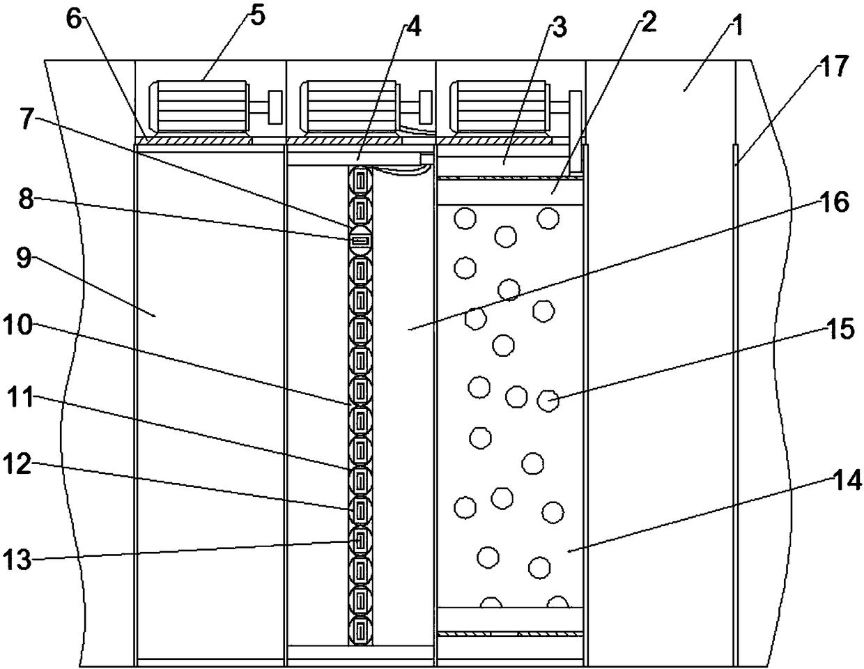
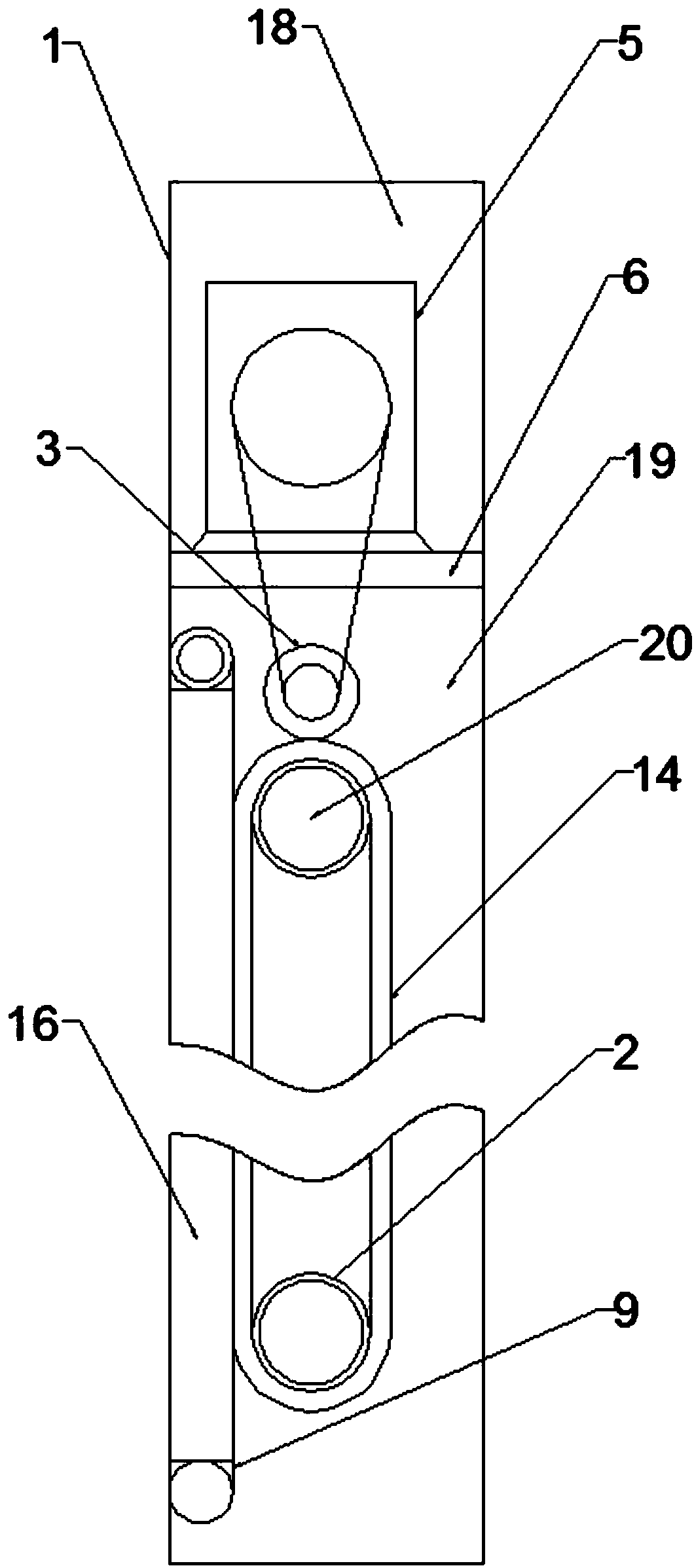
[0017] The reference signs in the accompanying drawings of the specification include: side chain case 1, transmission wheel 2, drive wheel 3, rotating shaft 4, motor 5, partition plate 6, safety airbag 7, safety switch 8, edge film 9, groove 10, airbag 11. Power supply 12, switch 13, belt 14, seepage hole 15, support plate 16, sealing strip 17, drive chamber 18, transmission chamber 19, accommodation chamber 20.

[0018] Embodiment, a kind of sponge foam production equipment, comprises conveying bottom chain plate, the side chain plate that is positioned at both sides of conveying bottom chain plate and carries out synchronous movement with the conveying bottom chain plate, such as figure 1 As shown, the side chain plate includes several laterally arranged side chain boxes 1, and a sealing strip 17 is fixed on the vertical side of the side chain box 1 towards the side of the conveyor bottom chain...


PUM


Abstract

The invention discloses sponge foam production equipment in the production field of sponge foam. The sponge foam production equipment comprises a conveying bottom chain plate and side chain plates; the side chain plates make synchronous motion with the conveying bottom chain plate; each side chain plate comprises a plurality of side chain boxes; the interior of each side chain box is divided intoa driving chamber at the upper part and a transmission chamber at the lower part; a motor is arranged in each driving chamber; one side, facing the conveying bottom chain plate, of each transmission chamber is opened; transmission wheels connected with the output end of a motor is arranged in each transmission chamber; two transverse rotating shafts up and down are arranged on the outer side, facing the conveying bottom chain plate, of the transmission wheels; every two rotating shafts up and down are wrapped with annular edge films; the transmission wheels abut against the edge films; a plurality of air bags are arranged on the inner sides of the edge films in the vertical direction; a power source and a switch are arranged in air bag; the multiple power sources are connected in parallel;and the motors are connected the parallel power sources in series. Through innovation on the structure of an existing side chain plate, the problems that the top of a sponge foam finished product subjected to horizontal and continuous foaming production is arch and is not flat can be solved well.

Description

technical field [0001] The invention relates to the field of sponge foam production, in particular to a sponge foam production equipment. Background technique [0002] At present, the production of polyurethane plastic foam (commonly known as sponge) at home and abroad uses polyurethane as the main material and some chemical raw materials to stir and mix to produce chemical reactions. The chain plate and the side chain plate that move synchronously with the bottom chain plate accompany the material forward together. The chemical reaction is an exothermic reaction, and there is gas in the reaction product. Polyurethane is a thermosetting plastic. Therefore, as the material is transported, the heat generated by the chemical reaction will solidify the material itself, and the generated gas will expand the material into a sponge. The outside is already a mature craft. However, as the material gradually expands and solidifies upwards, the friction between the side chain plate a...

Claims


Application Information

Patent Timeline
IPC IPC(8): B29C44/28B29C44/60
CPCB29C44/28B29C44/60
Inventor 彭军
Owner 重庆致昌塑胶制品有限公司
Why Eureka
Try Eureka