Riveting composite die and riveting method utilizing riveting composite die

A composite mold and riveting technology, which is applied in the field of riveting composite molds and riveting using riveting composite molds, can solve the problems of narrow application area, low connection efficiency, and large manufacturing damage, so as to achieve convenient positioning and installation, avoid damage, and improve the scope of application Effect

Active Publication Date: 2018-08-24
BEIJING INSTITUTE OF TECHNOLOGYGY
View PDF3 Cites 2 Cited by
  • Summary
  • Abstract
  • Description
  • Claims
  • Application Information

AI Technical Summary

Problems solved by technology

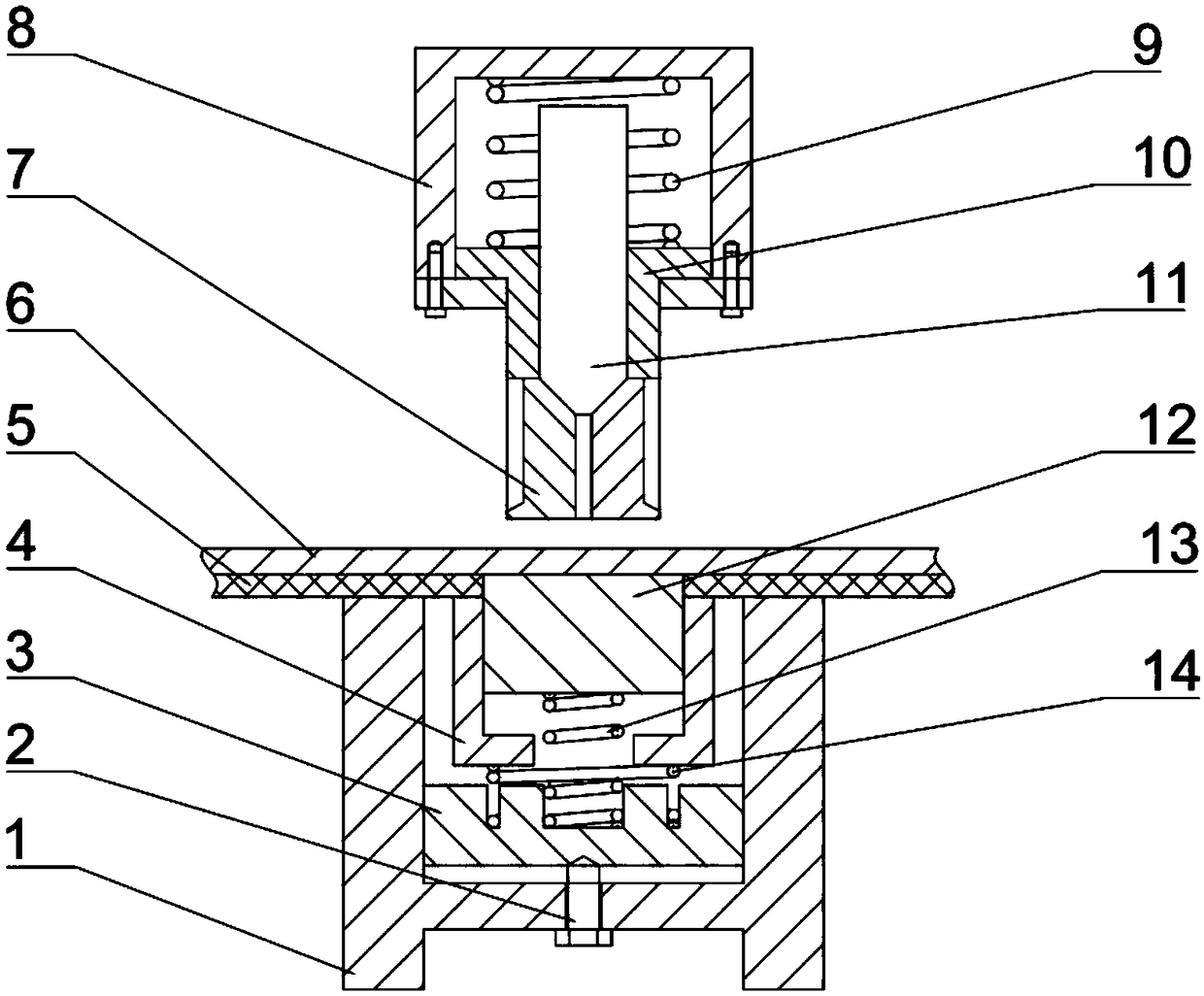
[0008] The purpose of the present invention is to provide a riveted composite mold and a riveting method using the riveted composite mold to solve the problems of low connection efficiency, large manufacturing damage and narrow applicable surface of the existing riveted composite mold

Method used

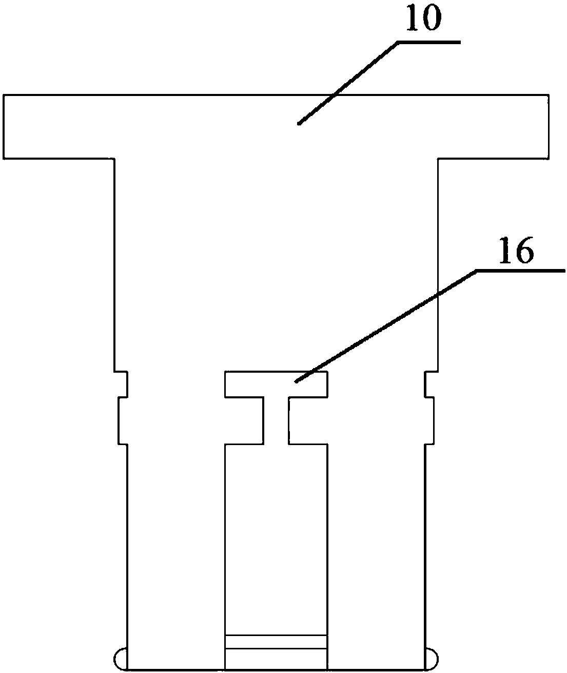
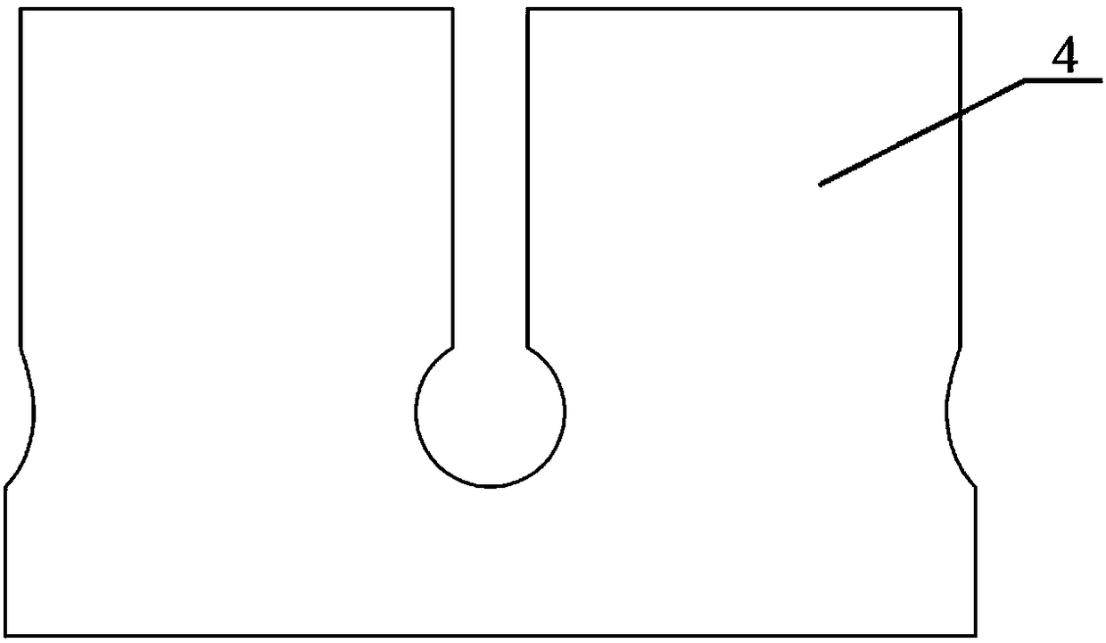

Image

  • Riveting composite die and riveting method utilizing riveting composite die
  • Riveting composite die and riveting method utilizing riveting composite die
  • Riveting composite die and riveting method utilizing riveting composite die

Examples


Embodiment Construction

[0033] The specific implementation manners of the present invention will be further described in detail below in conjunction with the accompanying drawings and embodiments. The following examples are used to illustrate the present invention, but are not intended to limit the scope of the present invention.

[0034] In the description of the present invention, it should be noted that unless otherwise specified and limited, the terms "installation", "connection" and "connection" should be understood in a broad sense, for example, it can be a fixed connection or a detachable connection. Connected, or integrally connected; it may be mechanically connected or electrically connected; it may be directly connected or indirectly connected through an intermediary, and it may be the internal communication of two components. Those of ordinary skill in the art can understand the specific meanings of the above terms in the present invention in specific situations.

[0035] Such as Figure...


PUM


Abstract

The invention relates to the technical field of automobile manufacturing, and discloses a riveting composite die and a riveting method utilizing the riveting composite die. The riveting composite diecomprises a lower base and a punch base. A limiting block is arranged on the inner side of the lower base, and a female die is arranged on the upper side of the limiting block. A positioning block isarranged in the female die. An outer layer punch is clamped to the lower end of the punch base. A middle jacking shaft is arranged in the outer layer punch in a sliding manner, and the lower end of the outer layer punch is connected with an expansion block. The riveting method comprises the following implementation steps that a riveting hole is prefabricated, the composite die is installed, and the punch base is downwards punched. Riveting hole prefabrication is conducted on a high-strength plate, composite die positioning installing is convenient, and high-strength plate damage in the riveting process is avoided; through the radial action on an aluminum alloy plate from the expansion block, non-rivet riveting composition between the aluminum alloy plate and the high-strength plate is achieved, and the riveting reliability and riveting efficiency are improved; and the composite die can be adjusted in real time according to the thickness of the high-strength plate and the aluminum alloyplate, the application range of the composite die is enlarged, and cost is reduced.

Description

technical field [0001] The invention relates to the technical field of automobile manufacturing, in particular to a riveting composite mold and a riveting method utilizing the riveting composite mold. Background technique [0002] In recent years, the automobile industry has developed rapidly, and the production and ownership of automobiles have increased rapidly. The resulting negative impact has also been highlighted, mainly in terms of energy and the environment. In order to save energy, protect the environment, and reduce carbon emissions, the use of lightweight technology has become an inevitable choice. The three aspects of material, structure and process are the main methods to realize lightweight technology. The materials mainly include lightweight alloys (such as aluminum alloys, magnesium alloys, etc.), carbon fiber composite materials, advanced high-strength steel, etc., and the application of the above new materials must solve Dissimilar material connection prob...

Claims


Application Information

Patent Timeline
Patent Type & Authority Applications(China)
IPC IPC(8): B29C65/56B29C33/00
Inventor 陈潇凯郭子煜李孟强
Owner BEIJING INSTITUTE OF TECHNOLOGYGY
Why Eureka
Try Eureka