Electric wire pay-off device for architectural decoration and finishing

A wire pay-off device and wire technology are applied in the field of wire pay-off devices for building decoration, which can solve the problems of unsuitable wire pay-off devices and inconvenient replacement of electric coils with different inner diameters, so as to avoid manual pay-off, prevent slippage, The effect of increasing friction

Inactive Publication Date: 2018-08-24
浙江富海建筑装饰工程股份有限公司
View PDF0 Cites 6 Cited by
  • Summary
  • Abstract
  • Description
  • Claims
  • Application Information

AI Technical Summary

Problems solved by technology

[0005] In view of this, what this application is to solve is the technical problem that the wire pay-off device in the conventional technology is not suitable for electric coils with different sizes and inner diameters and it is inconvenient to replace the electric coils

Method used


Image

  • Electric wire pay-off device for architectural decoration and finishing
  • Electric wire pay-off device for architectural decoration and finishing
  • Electric wire pay-off device for architectural decoration and finishing

Examples


Embodiment Construction

[0025] The implementation of the present application will be described in detail below with reference to the accompanying drawings and examples, so as to fully understand and implement the implementation process of how the present application uses technical means to solve technical problems and achieve technical effects.

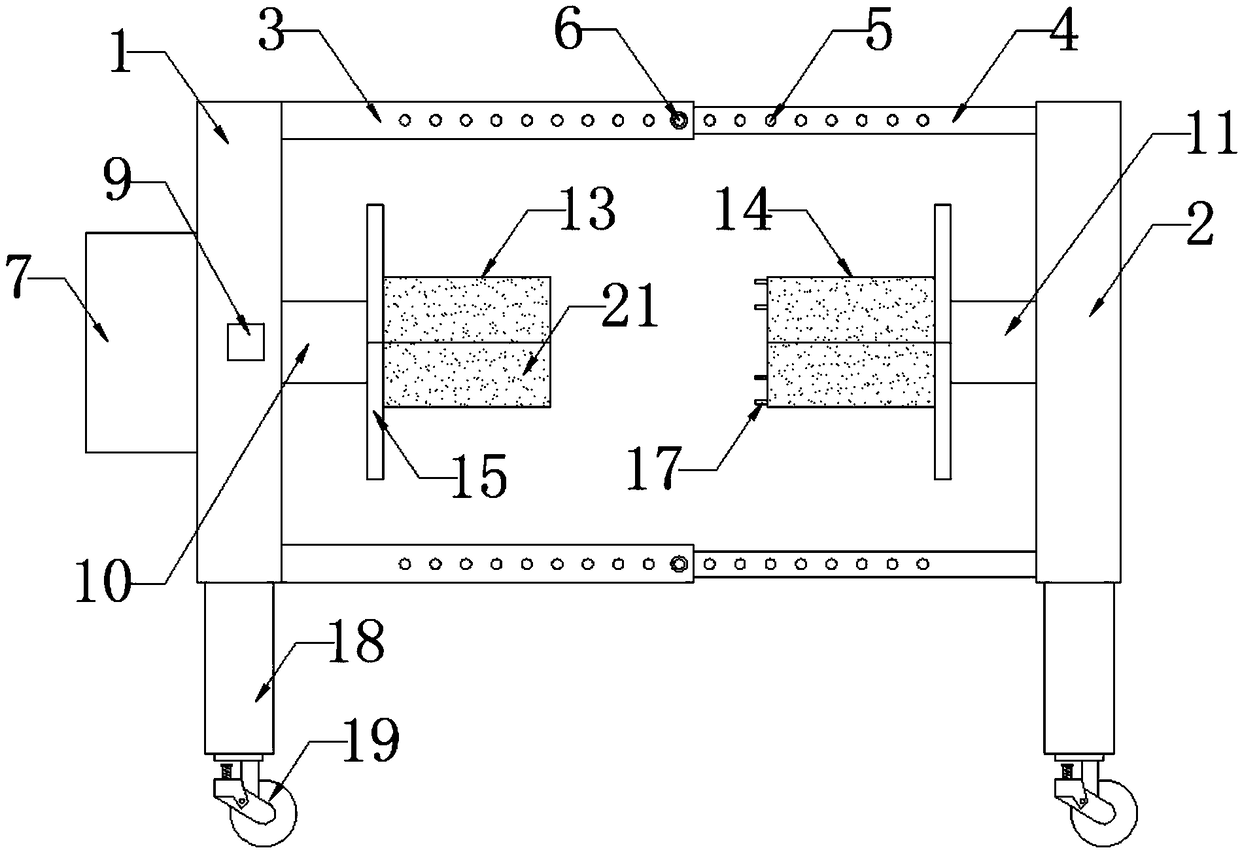
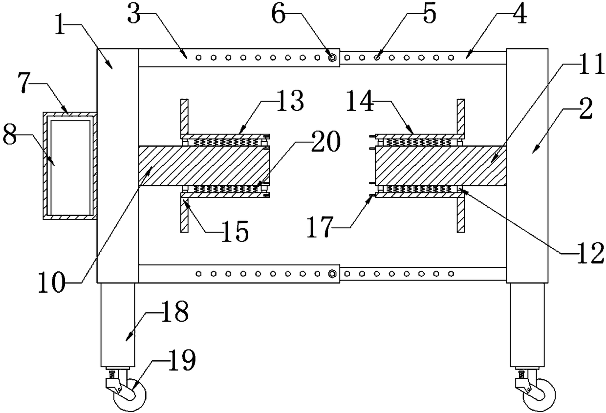
[0026] Such as Figure 1-3 As shown, a wire pay-off device for building decoration of the present invention includes a first fixed plate 1 and a second fixed plate 2, the four corners on one side of the first fixed plate 1 are respectively fixedly connected with one end of four outer tubes 3, the second The four corners on one side of the two fixing plates 2 are respectively fixedly connected with one end of the four inner pipes 4, and the middle part of the outer pipe 3 and the middle part of the inner pipe 4 are provided with several pin holes 5, and the other ends of the four outer pipes 3 are connected to each other. The pin shaft 6 passes through the pi...


PUM


Abstract

The invention discloses an electric wire pay-off device for architectural decoration and finishing. The electric wire pay-off device comprises a first fixed plate and a second fixed plate, wherein each of four corners at the side of the first fixed plate is fixedly connected with one end of a corresponding outer pipe, and each of four corners at the side of the second fixed plate is fixedly connected with one end of a corresponding inner pipe; the other end of each outer pipe is fixedly connected with the other end of the corresponding inner pipe by enabling a hinge pin to penetrate through ahinge pin hole, the middle portion of one side of the first fixed plate is rotationally connected with one end of a first rotating shaft through a bearing pedestal, and the middle portion of one sideof the second fixed plate is rotationally connected with one end of a second rotating shaft through a bearing pedestal; and the outer portion of the first rotating shaft is fixedly connected with theinner sides of two first arc-shaped plates through four electric telescopic rods, and the outer portion of the second rotating shaft is fixedly connected with the inner sides of two second arc-shapedplates through four electric telescopic rods. According to the electric wire pay-off device for architectural decoration and finishing, the distance between the two first arc-shaped plates and the distance between the two second arc-shaped plates can be adjusted by adjusting lengths of the electric telescopic rods, and therefore the electric wire pay-off device can be applied to electric wire coils with different sizes and inner diameters.

Description

technical field [0001] The application belongs to the technical field of building decoration, and in particular relates to a wire pay-off device for building decoration. Background technique [0002] Wire and cable are wire products that transmit electrical energy, electrical signals and realize electromagnetic energy conversion. Cables are usually composed of a cable core that transmits electrical power or electrical signals and a sheath that plays a protective and insulating role. It only contains one cable core and has a thinner diameter. Cables are usually called wires, and some wires do not have an insulating sheath and are called bare wires. The core in the cable is made of a metal material with good electrical conductivity. [0003] Most wire pay-off devices currently on the market are not suitable for electric coils with different sizes and inner diameters. During the unwinding process, the electric coils are prone to slippage, and the wires rub against the rotating ...

Claims


Application Information

Patent Timeline
Patent Type & Authority Applications(China)
IPC IPC(8): B65H49/20B65H67/02
CPCB65H49/20B65H67/02B65H2701/34
Inventor 顾晓栋唐焕一杨建飞周孝和陈鑫和
Owner 浙江富海建筑装饰工程股份有限公司
Why Eureka
Try Eureka