
Material conveying device for top of crane

A technology for conveying devices and materials, which is applied in the direction of conveyors, transportation and packaging, and load hanging components, etc. It can solve problems such as unstable connection of hanging pans, easy falling off of materials, and potential safety hazards, and achieves convenient and quick disassembly, and convenient assembly and disassembly , Use safe and stable effect

Inactive Publication Date: 2018-08-24
沈红如
View PDF0 Cites 0 Cited by
  • Summary
  • Abstract
  • Description
  • Claims
  • Application Information

AI Technical Summary

Problems solved by technology

[0002] Cranes are commonly used material transportation tools on construction sites. They are often used for high-altitude operations. The top of the crane is often equipped with a conveying device to transport the materials to be transported to the designated location. However, the existing materials used on the top of the crane There are still some defects in the use of the conveying device. The hanging plate at the bottom of the device is often only used to hang the material in the form of a hook, which causes the material to fall off easily during use, thus posing a certain safety hazard, and the connection of the hanging plate is also unstable and easy to fall off. Shortcomings

Method used


Image

  • Material conveying device for top of crane
  • Material conveying device for top of crane
  • Material conveying device for top of crane

Examples


Embodiment Construction

[0019] The preferred embodiments of the present invention will be described in detail below in conjunction with the accompanying drawings, so that the advantages and features of the present invention can be more easily understood by those skilled in the art, so as to define the protection scope of the present invention more clearly.

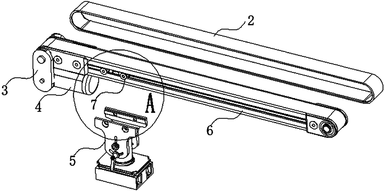
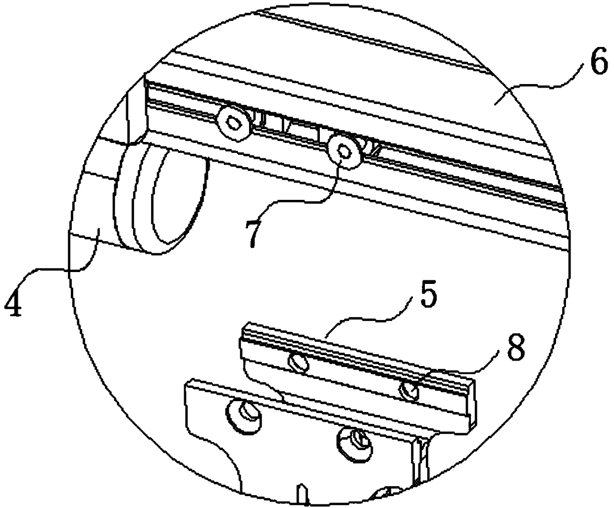
[0020] like Figure 1 to Figure 5 As shown, the material conveying device 1 used on the top of the crane includes a base 3, a conveyor belt 6 is arranged on the base 3, a crawler belt 2 is sleeved on the conveyor belt 6, and a motor 4 is installed at one end of the bottom of the conveyor belt 6. And two joints 7 are installed between the upper and lower ends of the conveyor belt 6, and a socket 5 is sleeved on the two joints 7, and two joint holes 8 are arranged on the outer wall of the top of the joint seat 5, and the two joint holes 8 A screw hole 17 is arranged below, an arc groove 18 is arranged below the screw hole 17, a base 9 is installed ...


PUM


Abstract

The invention discloses a material conveying device for the top of a crane. The device comprises a base seat, the base seat is provided with a conveyor belt, a crawler belt sleeves the conveyor belt,and a motor is arranged at one end of the bottom of the conveyor belt; two connecting holes are formed in the outer wall of the top of a connecting seat, and a locking screw rod is connected between the outer walls of the two sides of the middle of a bottom base in a penetrating mode, the bottoms of the two ends of the lock screw are correspondingly connected with hooks, and a hanging plate is clamped at the bottom of the bottom base; and clamping grooves are formed in the four edges of the outer wall of the top of the hanging plate, a fixing hole is formed in the top of the hanging plate, andtwo through holes are formed inside the hanging plate. The material conveying device for the top of the crane has the advantages that the bottom base with a column-shaped structure is arranged at thebottom of the connecting seat, the connecting seat is fixedly connected with the bottom base through a screw in a penetrating mode, and the bottom of the screw penetrates the lock screw rod penetrates through the the connecting seat and the bottom base is arranged at the bottom of the screw, the bottom of the lock screw rod is connected with the hooks which are obliquely arranged, so that the connecting seat and the bottom base can be connected more safely and stably.

Description

technical field [0001] The present invention relates to a material conveying device, more precisely, a material conveying device for the top of a crane. Background technique [0002] Cranes are commonly used material transportation tools on construction sites. They are often used for high-altitude operations. The top of the crane is often equipped with a conveying device to transport the materials to be transported to the designated location. However, the existing materials used on the top of the crane There are still some defects in the use of the conveying device. The hanging plate at the bottom of the device is often only used to hang the material in the form of a hook, which causes the material to fall off easily during use, thus posing a certain safety hazard, and the connection of the hanging plate is also unstable and easy to fall off. Shortcomings. Contents of the invention [0003] The present invention mainly solves the technical problems existing in the prior a...

Claims


Application Information

Patent Timeline
IPC IPC(8): B66C11/04B66C1/10B65G25/06
CPCB66C11/04B65G25/06B66C1/10
Inventor 沈红如
Owner 沈红如
Learn More