Steel structure anti-collapse joint
A technology of anti-collapse and steel structure, applied in the direction of building structure, construction, etc., can solve the problems of low ductility, structural collapse, high rigidity, etc., and achieve the effect of improving service life and avoiding fracture
- Summary
- Abstract
- Description
- Claims
- Application Information
AI Technical Summary
Problems solved by technology
Method used
Image
Examples
Embodiment 1
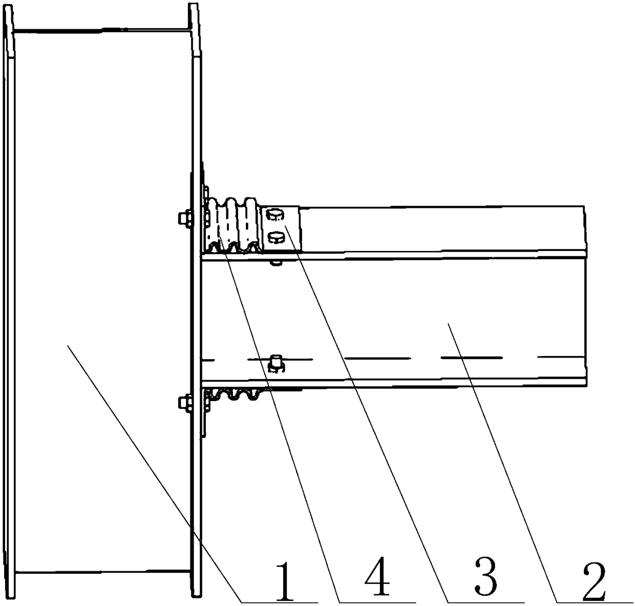
[0028] refer to image 3 , the main structure 1 is an H-shaped steel column, and the rod 2 is an H-shaped steel beam, wherein the end face of the H-shaped steel beam is fixed on the flange of the H-shaped steel column, and the corrugated connector 3 includes a first corrugated The cover plate and the second corrugated cover plate, wherein, the middle part of the first corrugated cover plate and the middle part of the second corrugated cover plate are corrugated structures 4, and the side of one end of the first corrugated cover plate is fixed to the H-shaped corrugated cover plate by first bolts. On the upper flange of the steel beam, the side of the other end of the first corrugated cover plate is bent upwards and fixed on the flange of the H-shaped steel column by the second bolt; the side of one end of the second corrugated cover plate is fixed on the H-shaped steel column by the third bolt On the lower flange of the shaped steel beam, the side of the other end of the secon...
Embodiment 2
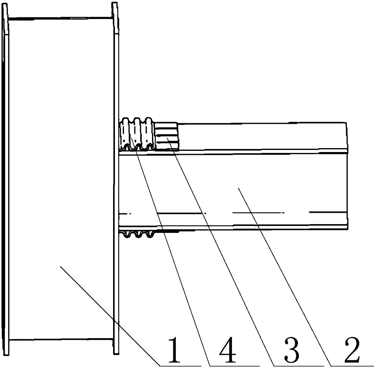
[0030] refer to figure 2 , the main structure 1 is an H-shaped steel column, and the rod 2 is an H-shaped steel beam, wherein the end face of the H-shaped steel beam is fixed on the flange of the H-shaped steel column, and the corrugated connector 3 includes a first corrugated The cover plate and the second corrugated cover plate, the middle part of the first corrugated cover plate and the middle part of the second corrugated cover plate are all corrugated structures 4, wherein the side of one end of the first corrugated cover plate is provided with a plurality of first grooves, The first corrugated cover plate is welded to the upper flange of the H-shaped steel beam through the weld welded in the first groove, and the other end of the first corrugated cover plate is welded to the flange of the H-shaped steel column; the second corrugated cover plate is welded to the flange of the H-shaped steel column; The side of one end of the cover plate is provided with several second gr...
Embodiment 3
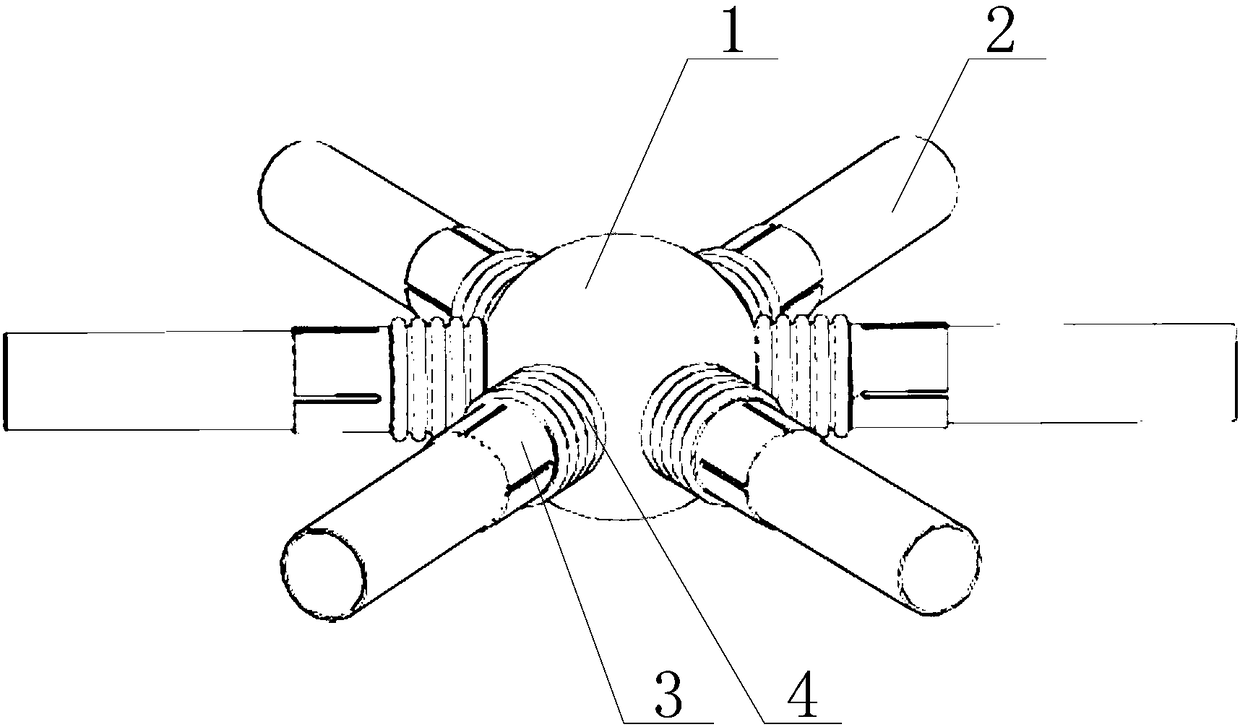
[0032] refer to figure 1 , the main structure 1 is a central sphere, the rod 2 is a steel pipe, the corrugated connector 3 is a tubular structure, the corrugated connector 3 is sleeved on the outer wall of the steel pipe, and the wall surface at one end of the corrugated connector 3 is provided with several first grooves , the corrugated connector 3 is welded on the outer wall of the steel pipe through the weld seam welded in the first groove, and the other end of the corrugated connector 3 is welded on the central sphere. It should be noted that the first grooves are equally spaced , the second grooves are distributed at equal intervals, and the first grooves and the second grooves are distributed along the axial direction, so as to prevent the welding heat-affected zone from concentrating on the same cross-section.
PUM
 Abstract
Description
Claims
Application Information
 - R&D
- Intellectual Property
- Life Sciences
- Materials
- Tech Scout
- Unparalleled Data Quality
- Higher Quality Content
- 60% Fewer Hallucinations
Browse by: Latest US Patents, China's latest patents, Technical Efficacy Thesaurus, Application Domain, Technology Topic, Popular Technical Reports.
© 2025 PatSnap. All rights reserved.Legal|Privacy policy|Modern Slavery Act Transparency Statement|Sitemap|About US| Contact US: help@patsnap.com


