Supercharge Your Innovation With Domain-Expert AI Agents!

A heat pipe steam generator for producing liquid medicine

A steam generator and heat pipe technology, applied in the field of heat pipes, can solve the problems of small heat absorption range at the evaporation end, low content of active ingredients, and low degree of intelligence, so as to improve the waste heat absorption capacity, prolong the service life, avoid local overheating or supercooling effect

Active Publication Date: 2019-04-09
青岛鑫众合贸易有限公司
View PDF8 Cites 0 Cited by
  • Summary
  • Abstract
  • Description
  • Claims
  • Application Information

AI Technical Summary

Problems solved by technology

The current evaporator is also widely used in the treatment of various diseases, especially in the treatment of chronic diseases caused by aging and old damage such as muscles and ligaments, such as the CN2167709Y patent, but in the current prior art, such as the CN2167709Y patent , because the steam generated directly by heating will cause the temperature of the generated steam to be too high, and it will cause too much moisture in the generated steam, and the drug may be deposited in the lower part because it is a particle, so the active ingredient in the ejected steam The content is too low, and the temperature is too high, and the degree of intelligence in the existing technology is not high, and effective intelligent operation cannot be carried out
[0005] In the prior art, when the heat pipe is used in the evaporator, the shape of the heat pipe affects the heat absorption area of ​​the evaporation end, so the heat absorption range of the evaporation end is generally relatively small, and sometimes multiple heat pipes need to be installed in the heat source to satisfy the heat absorption area. demand; and when there are multiple evaporating ends, each evaporating or condensing end will have uneven heat absorption due to the different positions of the heat source or cold source

Method used


Image

  • A heat pipe steam generator for producing liquid medicine
  • A heat pipe steam generator for producing liquid medicine
  • A heat pipe steam generator for producing liquid medicine

Examples


Embodiment Construction

[0049] The specific embodiments of the present invention will be described in detail below in conjunction with the accompanying drawings.

[0050] In this article, if there is no special explanation, when it comes to formulas, " / " means division, and "×" and "*" mean multiplication.

[0051] The specific embodiments of the present invention will be described in detail below in conjunction with the accompanying drawings.

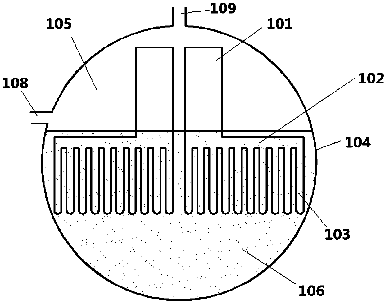
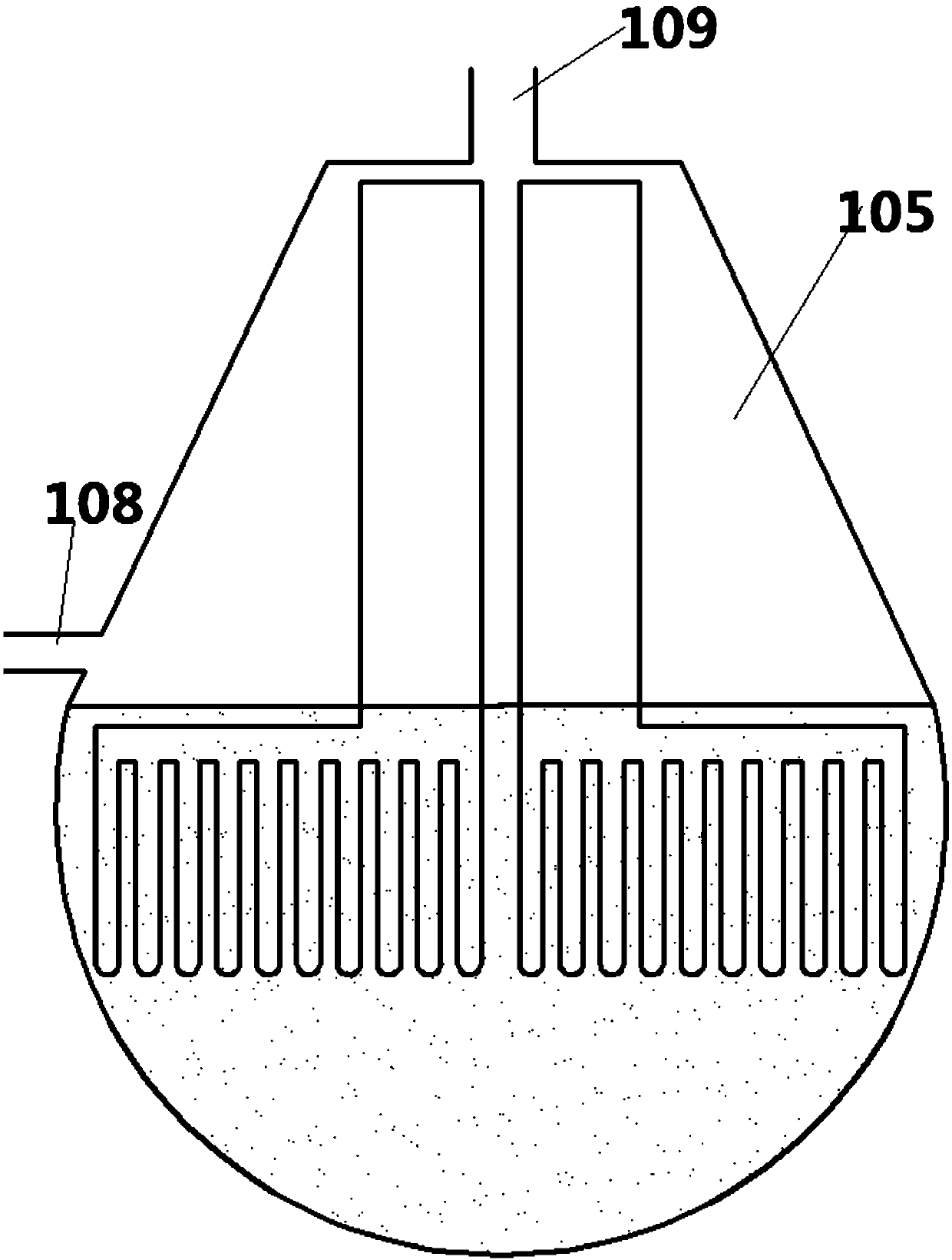
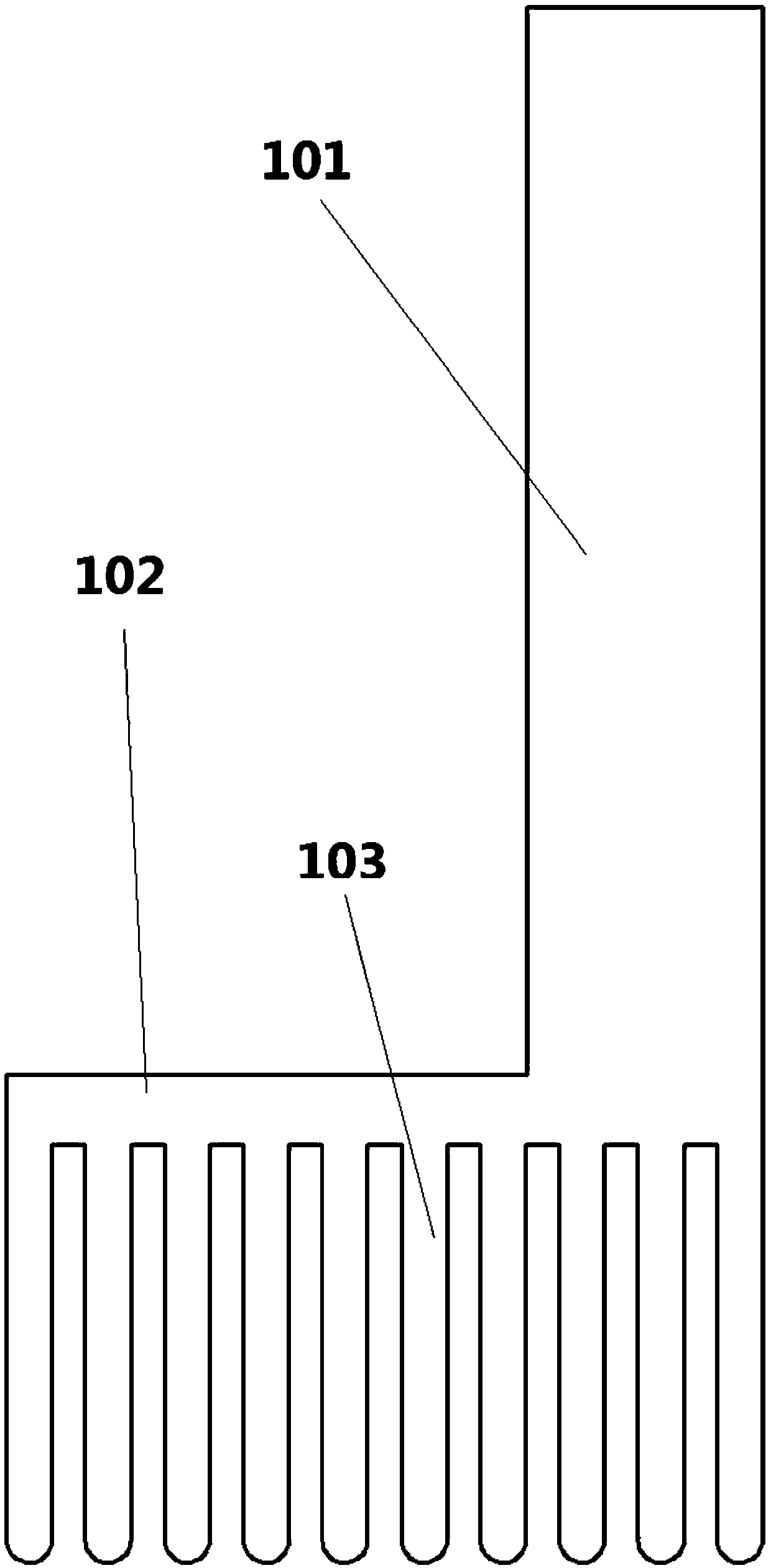
[0052] Such as Figure 1-8 A steam generator using heat pipes is disclosed, the steam generator includes a water tank 105 including a water inlet 108 and a steam outlet 109, and a heat pipe 10 including a vertical part 101, a horizontal part 102 and a vertical part 102. Straight pipe 103, wherein the bottom end of the vertical part 101 communicates with the horizontal part 102, and the horizontal part 102 extends from the bottom end of the vertical part 101 toward the direction away from the vertical part 101, and the bottom of the horizontal part 102 commun...


PUM


Abstract

The invention provides a heat pipe steam generator. The heat pipe steam generator comprises a water tank and a heat pipe, wherein the water tank comprises a water inlet and a steam outlet, and the heat pipe comprises a first vertical part, a horizontal part and a second vertical part; the bottom end of the first vertical part communicates with the horizontal part, the lower part of the horizontalpart communicates with a plurality of vertical pipes, the second vertical part is an evaporation end of the heat pipe, the first vertical part is a condensation end of the heat pipe, the first vertical part extends into the bottom of the water tank, and the second vertical part and the horizontal part are arranged in a heat source; and the first vertical part is composed of the multiple condensation pipes extending to the bottom of the water tank, and the lengths of the parts, extending to the water tank, of the condensation pipes are smaller and smaller in the flowing direction of the flue gas. According to the heat pipe steam generator, the lengths of the parts, extending to the water tank, of the condensation pipes are set to be different at different positions of the flue gas channel,so that the heat absorption capacity of the condensation pipes is continuously reduced in the flowing direction of the flue gas to be adapted to the heat absorption capacity of the vertical pipes, then the temperature of the whole heat pipe is kept basically the same in the flowing direction of the flue gas, therefore, the overall heat exchange efficiency is improved, the materials are saved, local damage caused by uneven temperature is avoided, and the service life of the heat pipe is prolonged.

Description

technical field [0001] The invention relates to a heat pipe technology, in particular to a heat pipe evaporator with a new structure. Background technique [0002] Heat pipe technology is a heat transfer element called "heat pipe" invented by George Grover of Los Alamos National Laboratory in the United States in 1963. It makes full use of the principle of heat conduction and phase change medium. The rapid heat transfer properties of the heat pipe quickly transfer the heat of the heating object to the heat source, and its thermal conductivity exceeds that of any known metal. [0003] Heat pipe technology was widely used in aerospace, military and other industries before. Since it was introduced into the radiator manufacturing industry, people have changed the traditional radiator design ideas and got rid of the single heat dissipation mode that only relies on high air volume motors to obtain better heat dissipation. The use of heat pipe technology enables the radiator to ob...

Claims


Application Information

Patent Timeline
Patent Type & Authority Patents(China)
IPC IPC(8): F28D15/02
CPCF28D15/02
Inventor 王淼胡全君赵明伟邹振宁崔林冷学力
Owner 青岛鑫众合贸易有限公司
Features
  • R&D
  • Intellectual Property
  • Life Sciences
  • Materials
  • Tech Scout
  • Unparalleled Data Quality
  • Higher Quality Content
  • 60% Fewer Hallucinations
Learn More