Portable support frame for surveying and mapping

A support frame and portable technology, which is applied in the field of portable support frames for surveying and mapping, can solve problems such as difficult adjustment, complicated adjustment methods, and reduced measurement efficiency, and achieve the effect of increasing the fine-tuning range, expanding the range of fine-tuning, and increasing the gain

Inactive Publication Date: 2018-08-24
中博宇图信息科技有限公司
View PDF9 Cites 5 Cited by
  • Summary
  • Abstract
  • Description
  • Claims
  • Application Information

AI Technical Summary

Problems solved by technology

The structure is small and easy to carry, but the fixed structure has the problem of difficult adjustment. For this problem:
Although this structure can precisely adjust the levelness and height of the laser total station, the adjustment method is relatively complicated, which reduces the efficiency of measurement

Method used


Image

  • Portable support frame for surveying and mapping
  • Portable support frame for surveying and mapping
  • Portable support frame for surveying and mapping

Examples


Embodiment 1

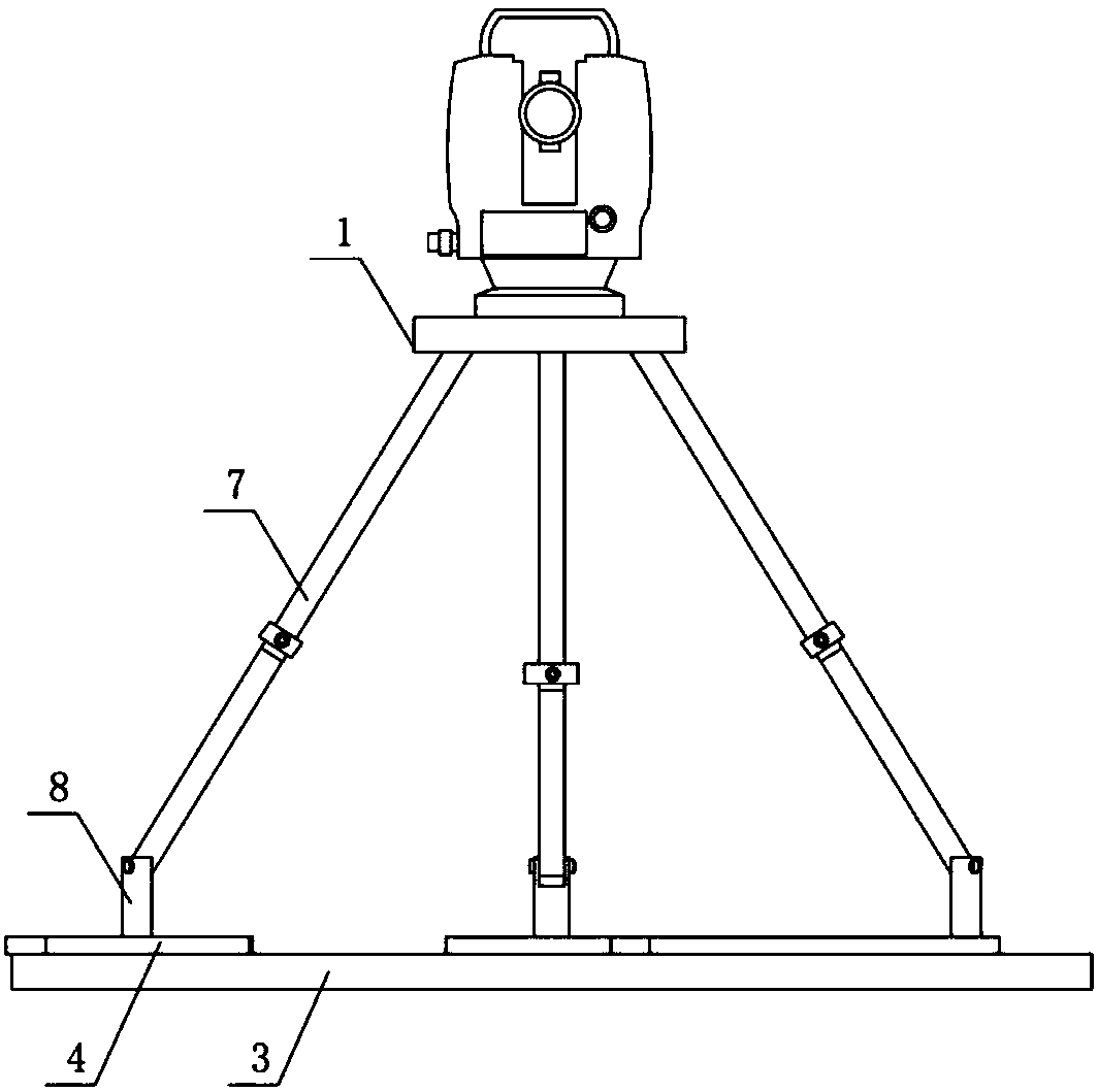
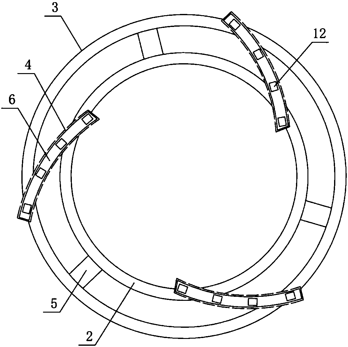
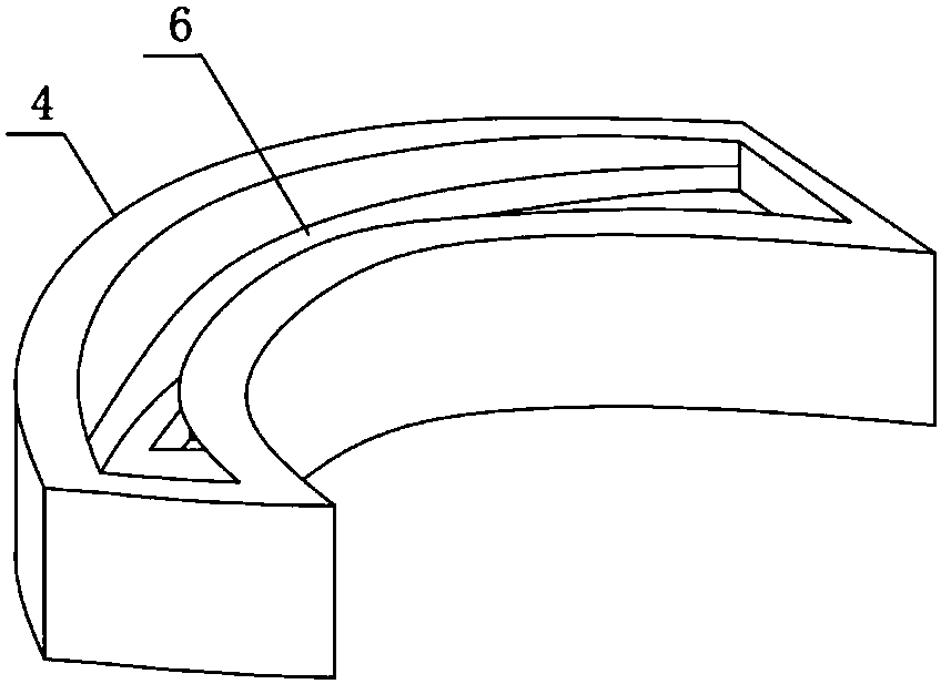
[0029] Such as Figure 1 to Figure 4 As shown, the present invention includes a support seat, a tripod and a stage 1, the support seat includes an inner support 2, an outer support 3 and an arc guide rail 4, and the inner support 2 and the outer support 3 are concentric ring structures, The inner support 2 and the outer support 3 are fixedly connected by three connecting rods 5, one end of the arc guide rail 4 is fixedly connected with the inner support 2, the other end of the arc guide rail 4 is fixedly connected with the outer support 3, and the arc guide rail The connection point between 4 and the inner support 2 is defined as A, the connection point between the arc guide rail 4 and the outer support 3 is defined as B, the connection points A and B are located on different radial lines, and the upper part of the arc guide rail 4 The end face is provided with an arc-shaped chute 6, and the depth of the arc-shaped chute 6 decreases successively in the direction from the conne...

Embodiment 2

[0031] The structure of this embodiment is basically the same as that of Embodiment 1, the difference is that: Figure 5 As shown, the lower end surface of the limit protrusion 11 is provided with a return spring 13, the return spring 13 is sleeved on the lower part of the slide bar 8, and is located in the chamber 10, the lower end of the slide bar 8 is provided with a first magnet 14, and the blind hole 12 The bottom end is provided with a second magnet 15 which is engaged with the first magnet 14 , and the attracting force between the first magnet 14 and the second magnet 15 is greater than the elastic force of the return spring 13 .

Embodiment 3

[0033] The structure of this embodiment is basically the same as that of Embodiment 1, the difference is that: Figure 6 As shown, the two ends of the arc-shaped guide rail are respectively connected to the first sliding seat 16 and the second sliding seat 17 through the rotating shaft. The cross-sections of the inner support and the outer support are both square structures for illustration. The first sliding seat 16 and the outer support The seat is slidably connected, and the second sliding seat 17 is slidably connected with the inner support.


PUM


Abstract

The invention discloses a portable support frame for surveying and mapping. The support frame comprises a support seat, a tripod and an objective table, wherein the support seat comprises an inner support seat, an outer support seat and arc-shaped guide rails; the inner support seat and the outer support seat adopt annular structures which are concentric and are fixedly connected through multipleconnection rods, one end of each arc-shaped guide rail is connected with the inner support seat, the other end of each arc-shaped guide rail is connected with the outer support seat, the connection point A of each arc-shaped guide rail and the inner support seat and the connection point B of each arc-shaped guide rail and the outer support seat are located on different radial lines, three arc-shaped guide rails are uniformly arranged in the circumferential direction, and arc-shaped sliding chutes are formed in the upper end surfaces of the arc-shaped guide rails; the tripod comprises three telescopic rods, the lower ends of the telescopic rods are hinged with sliding rods, the sliding rods are in gliding fit with the arc-shaped sliding chutes, multiple blind holes are formed in the bottomsof the arc-shaped sliding chutes, and the lower end of the sliding rods are in inserting fit with the blind holes. By means of the eccentric arc-shaped guide rails, accurate fine adjustment of the height of the whole support device is realized, and the support seat is light in weight and convenient to carry.

Description

technical field [0001] The invention belongs to the technical field of surveying and mapping equipment, in particular to a portable support frame for surveying and mapping. Background technique [0002] Surveying is all about measuring and drawing. Based on computer technology, optoelectronic technology, network communication technology, space science, and information science, with global navigation satellite positioning system (GNSS), remote sensing (RS), and geographic information system (GIS) as the technical core, the existing characteristics of the ground Points and boundaries obtain graphics and position information reflecting the current status of the ground through measurement means, which are used for planning, design and administrative management of engineering construction. [0003] In the process of measuring with equipment such as theodolite or total station, it is necessary for the surveyor to continuously adjust and record. In order to reduce the measurement ...

Claims


Application Information

Patent Timeline
Patent Type & Authority Applications(China)
IPC IPC(8): G01C15/00F16M11/32
CPCF16M11/32G01C15/00
Inventor 杨娟李培鹏王亚利
Owner 中博宇图信息科技有限公司
Why Eureka
Try Eureka