
Magnetoelastic torque sensor

A technology of torque sensor and magnetic field sensor, applied in instruments, piezoelectric/electrostrictive/magnetostrictive devices, torque measurement, etc., can solve the problems of inability to record magnetic field changes, loss of additional information of external magnetic fields, etc.

Active Publication Date: 2018-08-24
NCTE
View PDF11 Cites 2 Cited by
  • Summary
  • Abstract
  • Description
  • Claims
  • Application Information

AI Technical Summary

Problems solved by technology

Therefore, changes in the magnetic field in other directions cannot be recorded
In the process, additional information, for example about the influence of external forces or external magnetic fields, is gradually lost

Method used


Image

  • Magnetoelastic torque sensor
  • Magnetoelastic torque sensor

Examples


Embodiment Construction

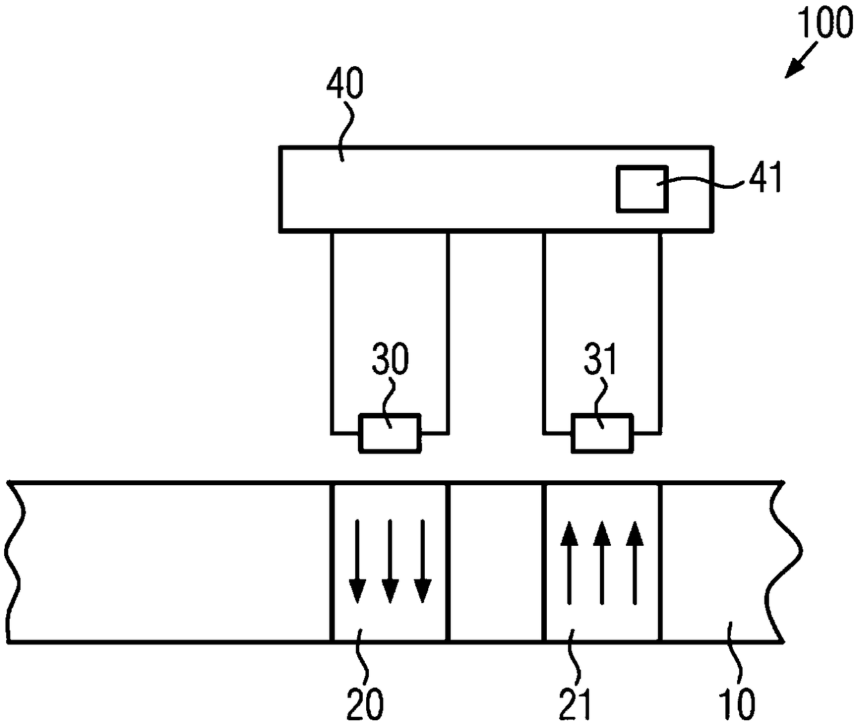
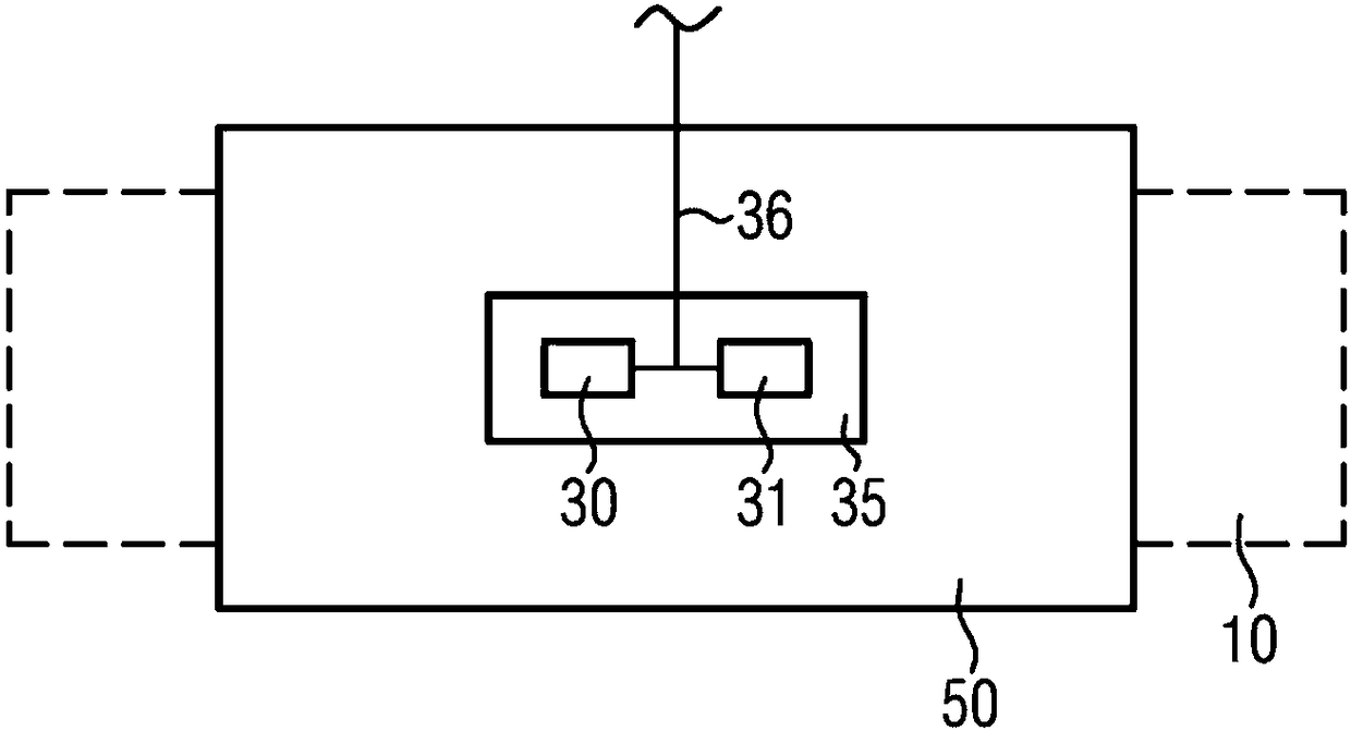
[0033] The invention relates to a structure for magnetoelastic measurement of torque consisting of a magnetically encoded shaft, two 3D-AMR sensors and a housing in which the two sensors are mounted. The invention also relates to a method for magnetoelastic measurement of torque. For the measurement, the main measured variable, namely the torque, is converted into a change in the magnetic field by magnetic encoding of the shaft. This magnetic field change will then be measured by means of the AMR sensor and an algorithm implemented in software will be used to draw conclusions about the torque.

[0034] By measuring with a 3D-AMR sensor with 3 measuring axes, the magnetic field changes in 3 directions under the action of torque can be recorded. In a preferred embodiment, two 3D-AMR sensors are used, which are mounted together with the evaluation electronics on the housing relative to the magnetic field of the measuring axis.

[0035] Such a magnetoelastic torque sensor is bas...


PUM

PropertyMeasurementUnit
Magnetic field strengthaaaaaaaaaa

Abstract

The present invention provides a magnetoelastic torque sensor. The magnetoelastic torque sensor includes a shaft that is magnetized in a first axial section in a first circumferential direction and towhich a torque to be measured can be applied; a first magnetic field sensor outside of the shaft for recording a magnetic field, which is generated by the first section of the shaft and independent of the applied torque. The first magnetic field sensor comprises a first 3D anisotropic magnetoresistance (3D-AMR) sensor.

Description

technical field [0001] The invention relates to a magnetoelastic torque sensor and a method for determining a torque applied to a shaft by a magnetoelastic torque sensor. Background technique [0002] The use of measuring coils is based on magnetostriction to measure changes in the magnetic field due to torque. The coils are non-contact mounted relative to the magnetically encoded measuring shaft (parallel to the axis of rotation) and record changes in the magnetic field due to magnetoelastic effects under load (reverse magnetostriction). The change in the magnetic field is proportional to the influence of the external force and is linked to the torque. [0003] The recording of the torsion angle is a state-of-the-art technique for torque measurement by means of AMR sensors. The AMR sensor is a magnetic field sensor that can measure the strength of a magnetic field based on the anisotropic magnetoresistance effect (AMR effect). At the end of the twisted track where the to...

Claims


Application Information

Patent Timeline
IPC IPC(8): G01L3/10
CPCG01L3/105G01R33/096G01L3/102H10N35/101
Inventor 卡洛斯·拉茨庞塞弗洛里安·埃克施拉格
Owner NCTE
Features
  • Generate Ideas
  • Intellectual Property
  • Life Sciences
  • Materials
  • Tech Scout
  • Unparalleled Data Quality
  • Higher Quality Content
  • 60% Fewer Hallucinations
Learn More