Self-pinned magnetic detecting element

a self-pinned, magnetic detection element technology, applied in the direction of magnetic measurement, data recording, nanomagnetism, etc., can solve the problems of inability to appropriately increase the recording density (more specifically, track recording density), the gmr effect cannot be enhanced, and the r/r value cannot be appropriately enhanced, so as to reduce the distortion and asymmetry of reproduction waveforms resulting from the fluctuations of magnetization, the effect of largely degrading the gm

Active Publication Date: 2005-12-22
TDK CORPARATION
View PDF5 Cites 6 Cited by
  • Summary
  • Abstract
  • Description
  • Claims
  • Application Information

AI Technical Summary

Benefits of technology

[0025] The CPP magnetic detecting element does not have an antiferromagnetic layer having a high specific resistance. Thus, it can prevent spin-independent scattering of conduction electrons caused by heat generation, and enhance the GMR effect, in comparison with the known CPP magnetic detecting element having a thick antiferromagnetic layer. Consequently, the reliability in energization can be increased. In addition, since the distance between shield layers disposed at the top and bottom of the CPP magnetic detecting element can be reduced, the CPP magnetic detecting element can be used for high track density recording on media.
[0057] The CPP structure in a magnetic detecting element allow the upper and lower surfaces of the pinned magnetic layer to lie between a nonmagnetic metal first magnetostriction-enhancing layer and second magnetostriction-enhancing layer, without degrading the GMR effect. Consequently, the magnetostriction coefficient of the pinned magnetic layer is increased from above and blow to produce appropriate magnetoelasticity, and the magnetization of the pinned magnetic layer is more firmly fixed. Consequently, magnetization of the pinned magnetic layer is not distorted by a longitudinal bias magnetic field from a hard bias layer, and accordingly the distortion and asymmetry of reproduction waveforms resulting from the fluctuations of the magnetization can be reduced. Also, the pinned magnetic layer is prevented from being reversed by electrostatic discharge. Thus, the performance and reliability of the resulting magnetic head can be enhanced.

Problems solved by technology

However, it has been found that the above-mentioned lattice vibration of conduction electrons causes phonon scattering to scatter the conduction electrons independently of the spin states, and that consequently the GMR effect represented by the ΔR / R value cannot be appropriately enhanced.
This makes it impossible to appropriately increase the recording density (more specifically, track recording density) of recording media.
Hence, the GMR effect cannot be enhanced.
Furthermore, Japanese Unexamined Patent Application Publication No. 8-7235 has not clearly disclosed the principle of how the tantalum buffer layer firmly fixes the magnetization of the pinned ferromagnetic layer.
Therefore, the structure of this publication cannot be directly applied for the structure of the CPP magnetic detecting element.
If the structure of the interface between the nonmagnetic material layer and the pinned magnetic layer is changed in the CIP magnetic detecting element, there is a high risk of reducing the ΔR / R value.
Since the Cu / CoFe interface produces an excellent spin-dependent interface scattering effect, it is impractical that, for example, another layer is disposed between the Cu layer and the CoFe layer to modify the Cu / CoFe interface structure of the CIP magnetic detecting element.

Method used


Image

  • Self-pinned magnetic detecting element
  • Self-pinned magnetic detecting element
  • Self-pinned magnetic detecting element

Examples


Embodiment Construction

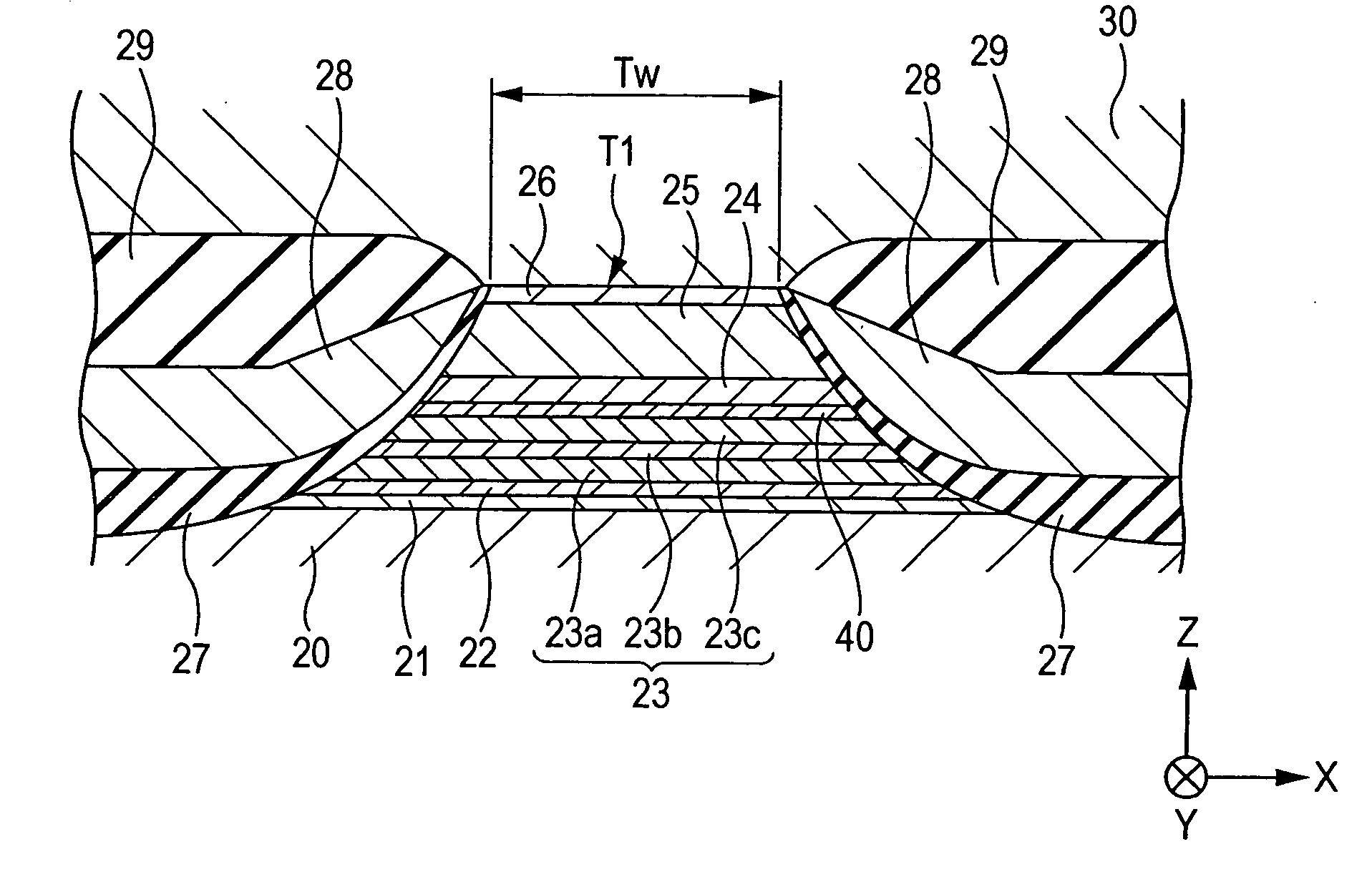
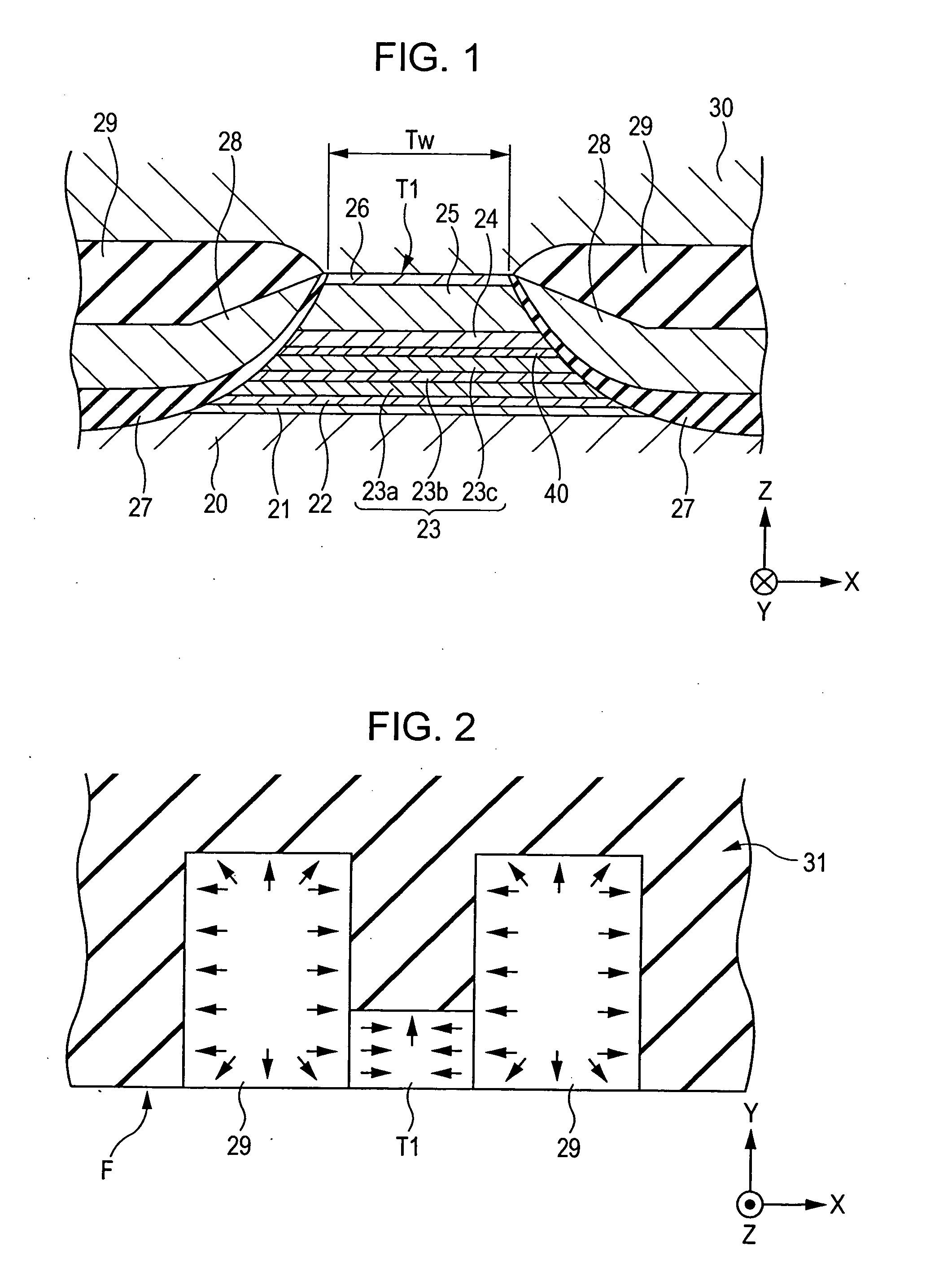
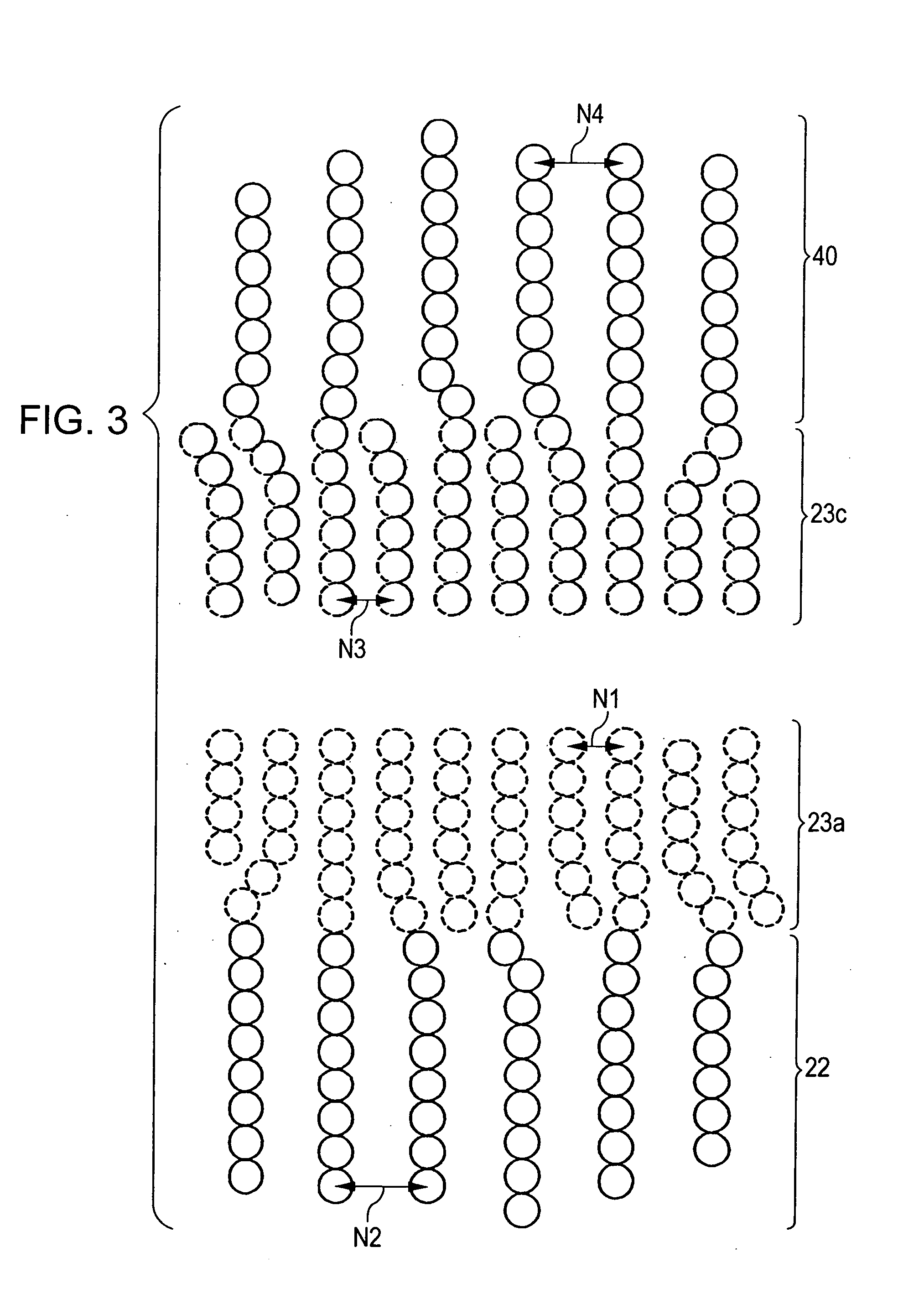
[0068]FIG. 1 is a sectional view of a magnetic detecting element according to a first embodiment of the present invention, viewed from the side surface opposing the recording medium, and FIG. 4 is a fragmentary schematic diagram of the magnetic detecting element shown in FIG. 1.

[0069] The magnetic detecting element shown in FIGS. 1 and 4 has a multilayer composite T1 on a lower shield layer 20 made of a magnetic material.

[0070] The multilayer composite T1 is formed by depositing a seed layer 21, a first magnetostriction-enhancing layer 22, a pinned magnetic layer 23, a second magnetostriction-enhancing layer 40, a nonmagnetic material layer 24, a free magnetic layer 25, and a protective layer 26 in that order on the shield layer 20.

[0071] The seed layer 21 is formed of a NiFe alloy, a NiFeCr alloy, Cr, Ta, or the like. For example, the seed layer 21 is formed of 60 atomic percent of Ni0.8Fe0.2 and 40 atomic percent of Cr to a thickness of 35 to 60 Å.

[0072] The seed layer 21 help...


PUM

PropertyMeasurementUnit
magneticaaaaaaaaaa
nonmagneticaaaaaaaaaa
magnetostrictionaaaaaaaaaa

Abstract

A CPP magnetic detecting element having a pinned magnetic layer whose magnetization is fixed by its uniaxial anisotropy in a structure that CIP magnetic detecting elements do not allow. In the CPP magnetic detecting element, the upper and lower surfaces of a pinned magnetic layer is disposed between nonmagnetic metal magnetostriction-enhancing layers. CPP magnetic detecting elements allow this structure without degrading the GMR effect. Thus, the magnetostriction coefficient of the pinned magnetic layer can be increased from above and below to produce an appropriate magnetoelasticity. Consequently, the magnetization of the pinned magnetic layer can be more firmly fixed.

Description

BACKGROUND OF THE INVENTION [0001] 1. Field of the Invention [0002] The present invention relates to CPP (current-perpendicular-to-the-plane) magnetic detecting elements, and particularly to a CPP magnetic detecting element having a structure which CIP (current-in-the-plane) magnetic detecting elements do not allow and in which the magnetization of a pinned magnetic layer is more firmly fixed by the uniaxial anisotropy of the pinned magnetic layer. [0003] 2. Description of the Related Art [0004] A magnetic detecting element having a multilayer composite including a free magnetic layer, a nonmagnetic material layer, and a pinned magnetic layer may be of a CIP type or a CPP type, according to the direction of current flowing in the multilayer composite. [0005] In a CIP magnetic detecting element, current flows in a direction parallel to the surfaces of the layers of the multilayer composite. In a CPP magnetic detecting element, current flows in the direction perpendicular to the surfa...

Claims


Application Information

Patent Timeline
Patent Type & Authority Applications(United States)
IPC IPC(8): G01R33/09G11B5/127G11B5/33G11B5/39
CPCB82Y10/00B82Y25/00G11B2005/3996G11B5/3932G01R33/093
Inventor HASEGAWA, NAOYASAITO, MASAMICHIUMETSU, EIJI
Owner TDK CORPARATION
Why Eureka
Try Eureka