Sound emission probe precise positioning device of rock uniaxial test and use method

A technology of precise positioning and acoustic emission, which is applied in the direction of material analysis using acoustic wave emission technology, measuring devices, and material analysis using sound waves/ultrasonic waves/infrasonic waves. Experimental requirements, flexible structure adjustment, and easy operation

Pending Publication Date: 2018-08-24
NORTHEASTERN UNIV +1
View PDF6 Cites 13 Cited by
  • Summary
  • Abstract
  • Description
  • Claims
  • Application Information

AI Technical Summary

Problems solved by technology

In experiments, researchers generally use existing positioning devices to fix AE probes on the surface of rock specimens, but most of these current devices cannot be adjusted, and sometimes cannot meet the needs of researchers; some researchers use glue , Adhesive tape to fix the ac

Method used


Image

  • Sound emission probe precise positioning device of rock uniaxial test and use method
  • Sound emission probe precise positioning device of rock uniaxial test and use method
  • Sound emission probe precise positioning device of rock uniaxial test and use method

Examples


Embodiment 1

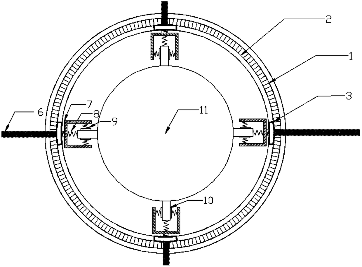
[0031] Embodiment 1: as Figure 1-5 As shown, a precise positioning device for an acoustic emission probe for rock uniaxial experiments is characterized in that it includes: an annular scale dial 1 , an annular vernier track 2 , a vernier 3 , and a probe containing cap 7 with a screw 6 .

[0032] The ring-shaped scale dial 1 is accurate to degrees and is used for positioning the acoustic emission probe, and there is a ring-shaped vernier track 2 on it.

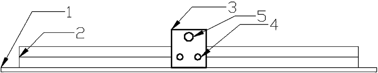
[0033] The circular vernier track 2 is located on the inner side of the circular scale dial 1, and there are four vernier 3 separated by 90 degrees, and the vernier 3 is fixed on the vernier track 2 by fixing screws 4.

[0034] The vernier 3 is connected with a probe containment cap 7 with a screw rod 6, the probe containment cap 7 is connected with the vernier 3 by the screw rod 6 and the threaded hole 5, and the probe containment cap 7 points to the inner side of the ring scale dial.

[0035] The probe containment cap 7 use...

Embodiment 2

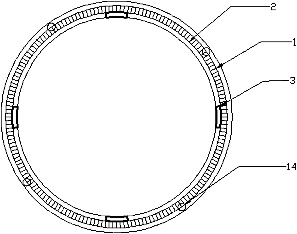
[0042] Embodiment 2: A precise positioning device for an acoustic emission probe for rock uniaxial experiments, including a ring scale dial 1, a ring vernier track 2, a vernier 3, a probe containing cap 7 with a screw 6, a scale rod 13, and a positioning hole 14.

[0043] Described annular scale dial 1 is accurate to degree, and comprises four positioning holes 14 on it, and scale bar 13 utilizes positioning hole 14 to connect two annular scale dials, and researchers can utilize scale bar 13 to determine two scale dials s position.

[0044] The circular vernier track 2 is fixed with three vernier 3 separated by 120 degrees, and the vernier 3 is fixed on the vernier track by fixing screws 4 .

[0045] The vernier 3 is connected with a probe containment cap 7 with a screw rod 6, the probe containment cap 7 is connected with the vernier 3 by the screw rod 6 and the threaded hole 5, and the probe containment cap 7 points to the inner side of the ring scale dial.

[0046] The prob...


PUM


Abstract

The invention discloses a sound emission probe precise positioning device of a rock uniaxial test and a use method. The device comprises an annular dial plate with a positioning hole and an annular nonius track, a nonius with a threaded hole and a set screw, a probe containing cap with a screw rod, and a scale bar; the nonius determines an orientation according to the annular dial plate; the annular dial plate is connected with the positioning hole by the scale bar; the scale bar has the effects of connecting and determining the position of the dial plate; one end, pointing to the inner side of the annular dial plate, of the screw rod is connected with the probe containing cap, and a sound emission probe is fixed by a spring (screw); during mounting, the screw rod is adjusted to increase frictional force between the probe and a rock test piece, and the probe and the positioning device are mounted on the surface of the rock test piece by using the frictional force. The device is flexible and convenient, and can perform sound emission probe precise positioning and fixing on rock test pieces with different shapes and sizes, meanwhile, the number and mounting orientation of the probe can be selected, and the time and vigor of researchers are effectively saved.

Description

technical field [0001] The invention relates to an acoustic emission probe positioning device, in particular to an adjustable acoustic emission probe positioning device which is easy to install and use, has low manufacturing cost and is used for rock uniaxial compression experiments. Background technique [0002] As my country's mineral resources become increasingly scarce, more and more mines are transferred to deep underground mining. While deep mining has brought us resources, it has also brought us many problems. Researchers need to further understand the mechanical properties of rock compression failure and crack evolution characteristics. [0003] During the failure process of rock materials, the internal damage of the material gradually accumulates, accompanied by elastic-plastic deformation, crack initiation and expansion, etc. These energy release processes generate high-frequency acoustic emission signals. Therefore, acoustic emission monitoring provides researcher...

Claims


Application Information

Patent Timeline
IPC IPC(8): G01N29/14G01N29/26
CPCG01N29/14G01N29/26G01N2291/0232
Inventor 李连崇姚鲁建余国锋韩云春薛俊华牟文强程关文
Owner NORTHEASTERN UNIV
Why Eureka
Try Eureka