A brushless DC motor rotor position detection circuit and detection method

A technology of rotor position detection and brushed DC motor, which is applied in the direction of electronically commutated motor control, electrical components, control systems, etc., can solve problems such as zero drift, inaccurate commutation time, integral error, etc., and achieve the effect of simple circuit

Active Publication Date: 2020-07-03
CHANGZHOU COLLEGE OF INFORMATION TECH
View PDF6 Cites 0 Cited by
  • Summary
  • Abstract
  • Description
  • Claims
  • Application Information

AI Technical Summary

Problems solved by technology

This method has the following defects: First, the hardware circuit is complex, especially the comparison circuit, which will cause zero point drift after long-term use; second, the filter circuit will cause the back EMF zero-crossing delay, and this delay changes with the speed of the motor The commutation results in inaccurate commutation time, which requires complex compensation methods; the third is that the compensated zero-crossing point needs to be delayed by 30 degrees to obtain the commutation time, and this delay needs to be adjusted continuously with the speed change of the motor to ensure its Accuracy, in order to eliminate the terminal voltage, it is necessary to add a low-pass filter, resulting in phase lag and commutation misalignment
[0004] In order to solve the aforementioned problems, many improved methods have been proposed in the industry. One is to eliminate the PWM pulse filter circuit by sampling the back EMF zero-crossing point when the PWM is turned on or off, but it still needs a delay of 30 degrees to obtain the replacement. phase moment
The second type uses an integral circuit to solve the 30-degree delay problem, but there is an integral error, which affects the accuracy; the third type is to directly obtain the commutation time by detecting the line voltage of the motor, but the phase shift problem caused by the filter circuit the problem still exists

Method used


Image

  • A brushless DC motor rotor position detection circuit and detection method
  • A brushless DC motor rotor position detection circuit and detection method
  • A brushless DC motor rotor position detection circuit and detection method

Examples


Embodiment 1

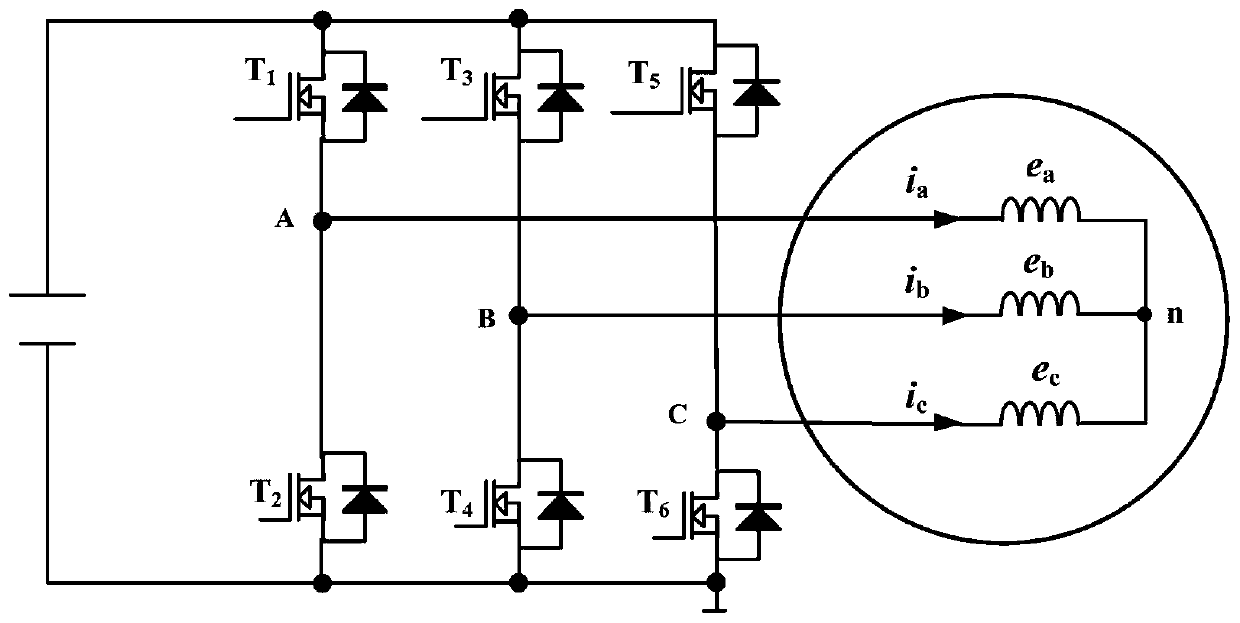
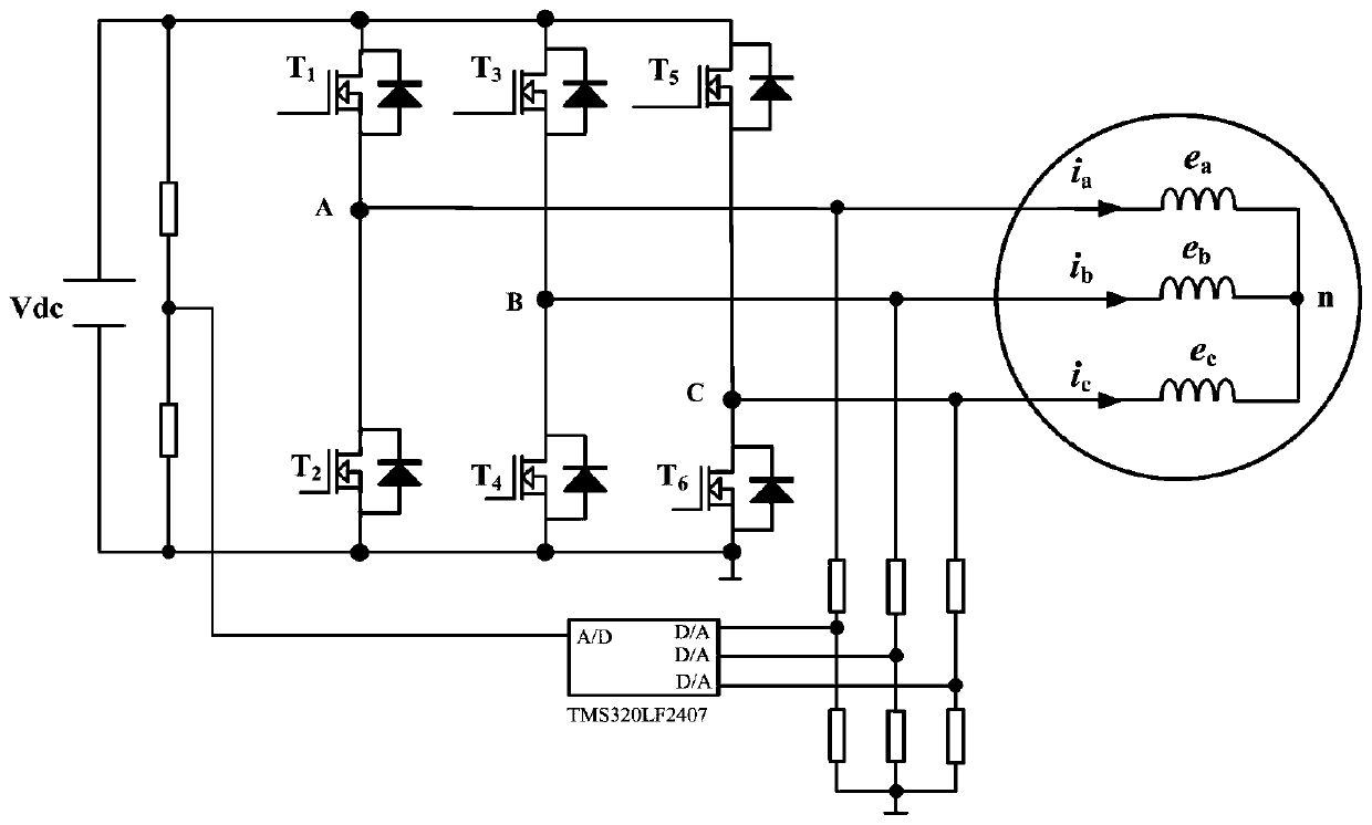
[0046] This example builds first image 3 In the circuit shown, a three-phase inverter is used to supply power to the brushless DC motor, and two resistors in series are respectively set at the DC bus voltage end of the three-phase inverter and the A, B, and C ends of the three-phase inverter. Four groups of resistor voltage divider networks are formed, the voltage of the DC bus voltage terminal and the divided voltage of the A, B, and C terminals of the three-phase inverter are input to the four A / Ds of the DSP controller TMS320LF2407 Analog-to-digital conversion terminal. The resistance values ​​of the eight resistors in the four-group voltage network are all 10K.

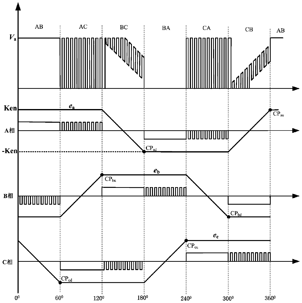
[0047] After the circuit is set up, the three-phase inverter starts to work, the PWM frequency is 20Hz, the sampling time is 5us, the control method adopts the front 60 degree constant current, the rear 60 degree PWM, and the motor back EMF coefficient ke is 0.20V / rpm. Obtain the reference voltage Vdc of the DC...


PUM


Abstract

The invention discloses a brushless direct current motor rotor position detecting circuit and a detecting method. The circuit uses a three-phase inverter to power a brushless direct current motor. Four resistor divider networks consisting of two resistors connected in series are arranged on the direct current bus voltage terminal of the three-phase inverter and the A, B and C terminals of the three-phase inverter respectively. The divided voltage of the direct current bus voltage terminal and the divided voltage of the A, B and C terminals of the three-phase inverter are input to a DSP controller. According to the invention, the circuit is simple; the hardware circuit is free of filtering, virtual neutral point constructing and 30-degree delay; the circuit simply needs several divider resistors and a DSP chip; direct current bus voltage is sampled and used as reference voltage; and three-phase output voltage is sampled.

Description

technical field [0001] The invention relates to a rotor position detection circuit and a detection method of a brushless direct current motor. Background technique [0002] Brushless DC motors have the advantages of high efficiency, high power, and easy maintenance. They need to detect the rotor position to ensure the synchronization of current and back EMF. [0003] At present, the most widely used rotor position detection methods without mechanical sensors mainly include back EMF zero-crossing detection method, flux linkage estimation method, and observer-based method. Among them, the counter electromotive force zero-crossing detection method is the most widely used and most mature method. In this method, the counter electromotive force zero-crossing signal is obtained by measuring the three-phase terminal voltage of the motor and comparing it with the constructed virtual neutral point after a PWM pulse filter circuit, and then obtaining the commutation point after a 30-d...

Claims


Application Information

Patent Timeline
Patent Type & Authority Patents(China)
IPC IPC(8): H02P6/182
CPCH02P6/182
Inventor 薛晓明时倩
Owner CHANGZHOU COLLEGE OF INFORMATION TECH
Why Eureka
Try Eureka