LED driving system

A LED drive and LED module technology, applied in the electronic field, can solve the problems of inability to adjust, shorten the service life of LED lamps, and low safety, and achieve the effects of energy saving, low cost, and simple circuit structure

Pending Publication Date: 2018-08-24
深圳市立智达智能科技有限公司
View PDF0 Cites 0 Cited by
  • Summary
  • Abstract
  • Description
  • Claims
  • Application Information

AI Technical Summary

Problems solved by technology

[0004] (1) Most of the existing LED drive systems do not have a soft-start scheme, but directly drive the LED lamp in the LED lamp, resulting in an instantaneous increase in the current flowing through the LED lamp, which has a great impact on the LED lamp itself, and is likely to cause The service life of the LED lamp is shortened, and even the LED lamp is damaged, that is, the safety is not high
[0005] (2) The existing LED drive system can only work at a fixed power and cannot be adjusted according to the surrounding environment. Maintaining high-power work for a long time causes a lot of energy waste

Method used


Image

  • LED driving system
  • LED driving system
  • LED driving system

Examples


Embodiment Construction

[0023] Below in conjunction with accompanying drawing and embodiment, further elaborate the present invention.

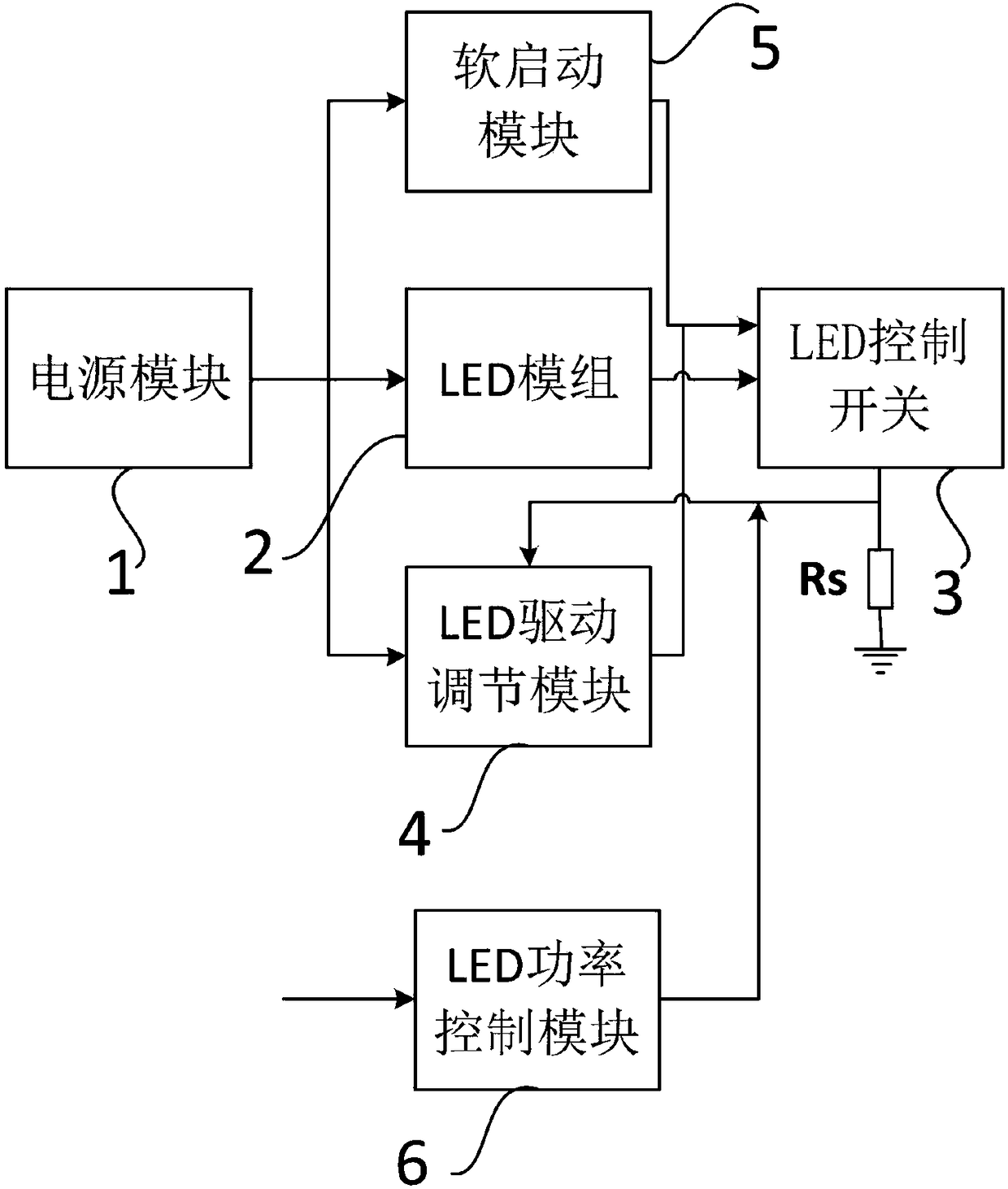
[0024] Such as figure 1 As shown, an LED drive system includes a power supply module 1 , an LED drive adjustment module 4 , an LED control switch 3 , a soft start module 5 , an LED module 2 , and an LED power control module 6 .

[0025] The power module 1, the LED module 2, and the LED control switch 3 are connected in sequence. The input end of the LED module 2 is connected to the voltage sampling input end of the LED drive adjustment module 4 . The output end of the LED control switch 3 is connected with the current sampling input end of the LED drive adjustment module 4 . The output end of the LED drive adjustment module 4 is connected to the control input end of the LED control switch 3 . The output terminal of the power supply module 1 is connected with the input terminal of the soft start module 5 . The output end of the soft start module 5 is connected wi...


PUM


Abstract

The invention discloses an LED driving system which comprises a power supply module, an LED driving adjustment module, an LED control switch, a soft start module and an LED module. The power supply module, the LED module and the LED control switch are sequentially connected. The input end of the LED module is connected with the voltage sampling input end of the LED driving adjustment module. The output end of the LED control switch is connected with the current sampling input end of the LED driving adjustment module. The output end of the LED driving adjustment module is connected with the control input end of the LED control switch. The output end of the power supply module is connected with the input end of the soft start module. The output end of the soft start module is connected withthe control input end of the LED control switch. The soft start module is used to soft start the LED module. The soft start module enables the LED module to be turned on at the zero crossing point ofalternating current to prevent the LED module from large current shock.

Description

technical field [0001] The invention relates to the field of electronic technology, in particular to an LED driving system. Background technique [0002] LED (Light Emitting Diode, Light Emitting Diode) is a new generation of light source that uses semiconductor materials as the electro-optical conversion medium. It has the characteristics of energy saving, environmental protection, long life and small size. It will soon replace energy-saving lamps and become the mainstream lighting. With the implementation of the global ban on production and sales of incandescent lamps, LED lighting will face the opportunity to replace incandescent lamps, with a market size of hundreds of billions. [0003] However, the existing LED drive system has the following deficiencies: [0004] (1) Most of the existing LED drive systems do not have a soft-start scheme, but directly drive the LED lamp in the LED lamp, resulting in an instantaneous increase in the current flowing through the LED lamp...

Claims


Application Information

Patent Timeline
IPC IPC(8): H05B33/08H05B44/00
CPCH05B45/00H05B45/37Y02B20/30
Inventor 季宁
Owner 深圳市立智达智能科技有限公司
Why Eureka
Try Eureka