Air duct dehumidifier and electrical cabinet dehumidifying method

A technology for dehumidifiers and electrical cabinets, which is applied to electrical components, structural parts of electrical equipment, cooling/ventilation/heating transformation, etc. It can solve the problems of low reliability of dehumidifiers and simple air duct structure, and achieve dehumidification reliability High, small size, and the effect of increasing the discharge speed

Pending Publication Date: 2018-08-24
湖南智热技术股份有限公司
View PDF3 Cites 1 Cited by
  • Summary
  • Abstract
  • Description
  • Claims
  • Application Information

AI Technical Summary

Problems solved by technology

The structure of the air duct in this scheme is too simple, and the reliability of the dehumidifier working in a high humidity environment for a long time is not high
[0006] To sum up, the dehumidifiers in the prior art cannot meet the demands of the wind power industry in terms of the air intake volume, dehumidification efficiency and dehumidification reliability. The electrical cabinet equipment is becoming more and more dense, and the internal space is becoming more and more compact, while the internal dehumidification efficiency requirements are lower. In order to solve the problem of dehumidification of the air in the electrical cabinet of the wind power industry and improve the dehumidification efficiency and dehumidification reliability, it is our goal to develop a dehumidifier that can be independently installed in the electrical cabinet and has its own air duct. purpose of the invention

Method used


Image

  • Air duct dehumidifier and electrical cabinet dehumidifying method
  • Air duct dehumidifier and electrical cabinet dehumidifying method
  • Air duct dehumidifier and electrical cabinet dehumidifying method

Examples


Embodiment Construction

[0031] Attached below Figures 1 to 6 Embodiments of the present invention are described in detail.

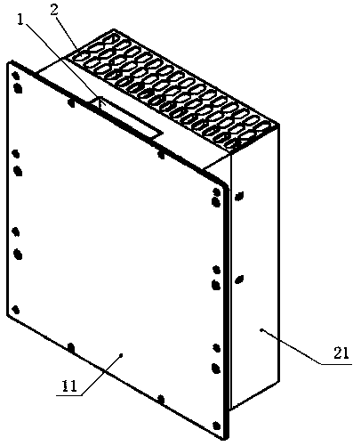
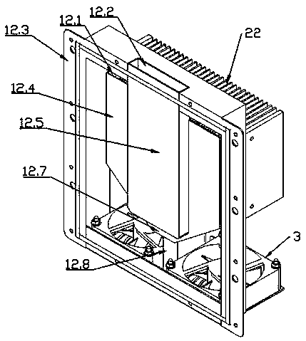
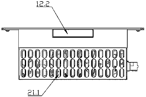
[0032] The air duct dehumidifier includes a cold end air duct 1 with a condensation dehumidification function and a hot end air duct 2 with a heating and dehumidification function, the cold end air duct 1 is fixed on the left or right side of the hot end air duct 2, and the cold The bottom of the end air duct 1 and the hot end air duct 2 are connected, and the fan 3 that can draw air inward is installed at the bottom where the cold end air duct 1 and the hot end air duct 2 are connected, and the external air is sent into the cold end air duct 1 and the hot end air duct. After being dehumidified in the end air duct 2, it is discharged.

[0033]As shown in the figure, the air duct dehumidifier draws in the external air through the fan 3, and the air that enters the cold end air duct 1 is condensed and dehumidified in the cold end air duct 1, and then becomes dry cold air and th...


PUM


Abstract

The invention provides an air duct dehumidifier and an electrical cabinet dehumidifying method. The air duct dehumidifier comprises a cold end air duct which has a condensation and dehumidification function and a hot end air duct which has a heating and dehumidifying function. The cold end air duct is fixed on the left side or the right side of the hot end air duct. The bottom parts of the cold end air duct and the hot end air duct are connected. Blowers capable of inward drawing the air are installed on the connected bottom parts of the cold end air duct and the hot end air duct to feed the external air into the cold end air duct and the hot end air duct to be dehumidified and then discharged. The air duct dehumidifier is compact in structure, small in size and low in weight and independent and complete in air duct structure and can work under the high humidity environment for a long time so as to be high in dehumidification efficiency and reliability and particularly suitable for theoccasion of high dehumidification requirement, limited air duct size and insufficient air volume and inconvenient maintenance.

Description

technical field [0001] The invention relates to an air duct dehumidifier, which belongs to the technical field of air conditioning, and also relates to a dehumidification method for an electrical cabinet. Background technique [0002] At present, there are many ways for electrical control cabinets to use air-cooling systems to cool their internal electronic components, and most of them are closed air-cooling systems with air ducts. If the humidity of the air in the air-cooling system is high, it will have a negative impact on the reliable operation of electronic components, reduce the reliability of electronic components, and even cause electronic components to be short-circuited and burned. Therefore, dehumidification equipment is generally required inside the electrical control cabinet to ensure the humidity in the cabinet. At present, there are mainly the following types of dehumidification equipment on the market: one is the dehumidifier using compression technology, wh...

Claims


Application Information

Patent Timeline
Patent Type & Authority Applications(China)
IPC IPC(8): H05K7/20
CPCH05K7/20136
Inventor 龙涛胡斌廖向前李纯
Owner 湖南智热技术股份有限公司
Why Eureka
Try Eureka