Compressing device for detection

A technology of pressing device and slide plate, which is applied in the direction of positioning device, workpiece clamping device, clamping, etc., can solve the problems of economic loss and breakage of the processed object of milling cutter, and achieve easy production and manufacturing, avoid economic loss and novel concept Effect

Inactive Publication Date: 2018-08-28
句容新禾五金电器有限公司
View PDF6 Cites 0 Cited by
  • Summary
  • Abstract
  • Description
  • Claims
  • Application Information

AI Technical Summary

Problems solved by technology

The clamps currently used are relatively tight for the processed items, which may easily cause the milling cutter or the processed items to break during the processing, resulting in huge economic losses.

Method used


Image

  • Compressing device for detection
  • Compressing device for detection
  • Compressing device for detection

Examples


Embodiment Construction

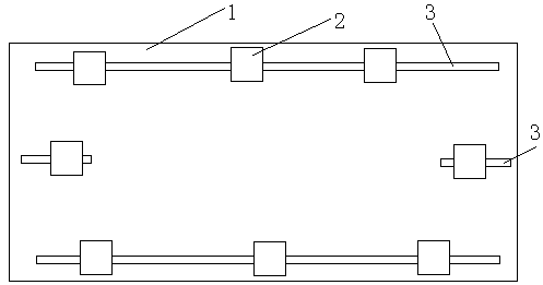
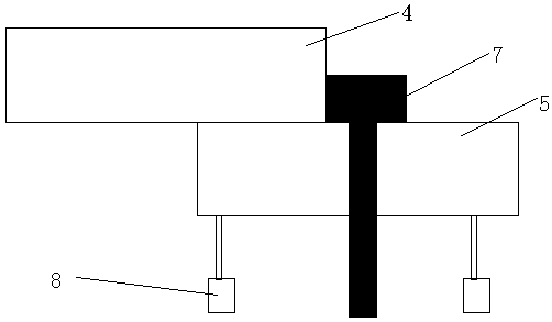
[0013] A pressing device for testing, comprising a base plate 1 and a plurality of slide plates 2, the left and right sides of the base plate are respectively provided with transverse chute 3, the front and rear sides of the base plate are respectively provided with transverse chute 3, the front and rear sides A number of slide plates are arranged on the horizontal chute, and a slide plate is respectively arranged on the horizontal chute on the left and right sides; Slot 6, the upper slide plate is slidably connected with the chute through the slider, the adjustment bolt 7 is arranged in the chute, and the slide block 8 is provided at the bottom of the lower slide plate, and the slide block is slidably connected with the corresponding transverse chute.

[0014] The bottom of the lower slide is provided with two sliding blocks, and the two slides are symmetrically arranged at the left and right positions of the bottom of the lower slide.


PUM


Abstract

A compressing device for detection comprises a bottom plate and a plurality of sliding plates, wherein transverse chutes are correspondingly formed in the left side, the right side, the front side andthe rear side of the bottom plate; the plurality of sliding plates are arranged on the transverse chutes in the front side and the rear side; one sliding plate is arranged on each of the transverse chutes in the left side and the right side; the sliding plates are of double-layer structures including upper layer sliding plates and lower layer sliding plates; the lower layer sliding plates are provided with hollow chutes; the upper layer sliding plates are in sliding connection with the chutes through sliding blocks; adjusting bolts are arranged in the chutes; sliding moving blocks are arranged at the bottom parts of the lower layer sliding plates and are in sliding connection with the corresponding transverse chutes. The device is simple and reasonable in structure, easy to produce and manufacture, ingenious in design, novel in idea, and capable of effectively fastening a workpiece; a milling cutter or a processed object is prevented from breaking and cracking, so that the economic loss is avoided.

Description

technical field [0001] The invention relates to a structure of a clamping device, in particular to a pressing device for testing. Background technique [0002] A milling machine mainly refers to a machine tool that uses a milling cutter to process various surfaces on a workpiece. Usually the rotation of the milling cutter is the main movement, and the movement of the workpiece (and) the milling cutter is the feed movement. It can process planes, grooves, various curved surfaces, gears, etc. A milling machine is a machine tool with a wide range of uses. It can process planes (horizontal planes, vertical planes), grooves (key slots, T-shaped slots, dovetail slots, etc.), toothed parts (gears, spline shafts, sprockets), Spiral surfaces (threads, spiral grooves) and various curved surfaces. In addition, it can also be used to process the surface and inner hole of the rotating body and perform cutting work. When the milling machine is working, the workpiece is installed on th...

Claims


Application Information

Patent Timeline
Patent Type & Authority Applications(China)
IPC IPC(8): B23Q3/06B25B11/00
CPCB23Q3/06B25B11/00
Inventor 赵月龙
Owner 句容新禾五金电器有限公司
Why Eureka
Try Eureka