
Anti-pull-break structure for injection mold

An injection mold and anti-pull-break technology, applied in the field of anti-pull-break structure of injection molds, to achieve the effect of improving product qualification rate, solving product breaking and simple structure

Pending Publication Date: 2018-08-28
江苏蔚金汽车零部件有限公司
View PDF9 Cites 2 Cited by
  • Summary
  • Abstract
  • Description
  • Claims
  • Application Information

AI Technical Summary

Problems solved by technology

[0002] When the injection molding of the product is completed, the coagulation material in the flow channel will stick to the injection nozzle on the female mold during the opening process of the male and female molds, but the normal state should be that the product and the coagulation material are in the male mold part and ejected by the thimble. The aggregate sticks to the master mold, so the product and the runner aggregate are in relative motion, and the product in the gate area is often broken during the mold opening process. The existing method is to only polish the runner side wall, which requires polishing. The technician’s action techniques are relatively standardized. Although the phenomenon of product sticking to the master mold can be improved to a certain extent after polishing, which can improve the product qualification rate, it cannot fundamentally solve the problem.

Method used


Image

  • Anti-pull-break structure for injection mold
  • Anti-pull-break structure for injection mold
  • Anti-pull-break structure for injection mold

Examples


Embodiment Construction

[0017] The following will clearly and completely describe the technical solutions in the embodiments of the present invention with reference to the accompanying drawings in the embodiments of the present invention. Obviously, the described embodiments are only some, not all, embodiments of the present invention. Based on the embodiments of the present invention, all other embodiments obtained by persons of ordinary skill in the art without making creative efforts belong to the protection scope of the present invention.

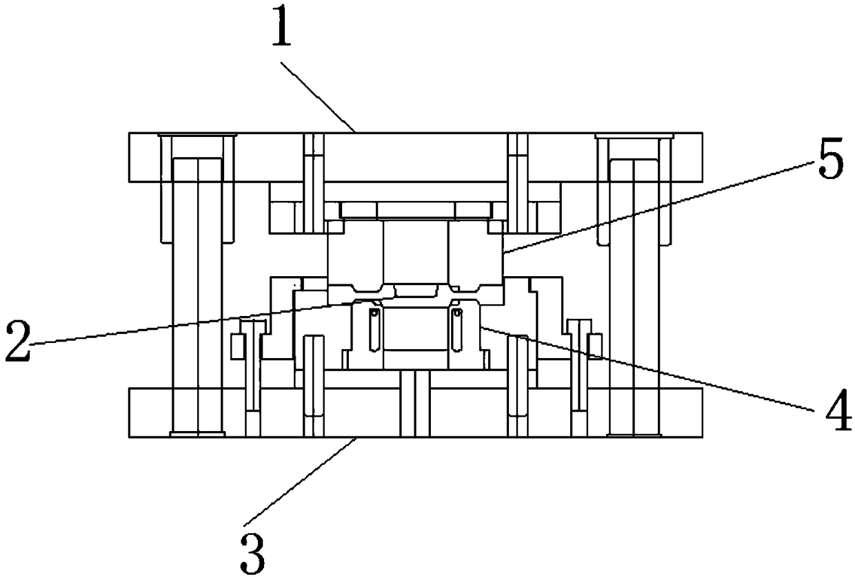
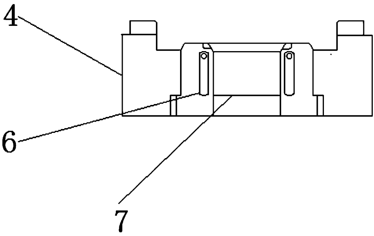
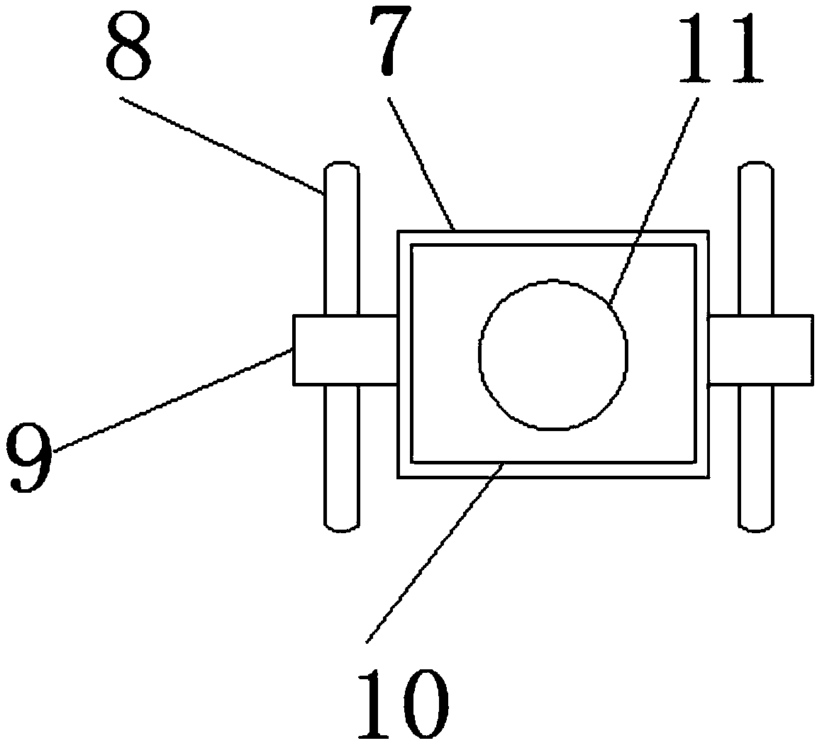
[0018] see Figure 1-4 , an embodiment provided by the present invention: an anti-breakage structure of an injection mold, comprising a lower mold outer ring 4 and an upper mold core 5, the upper end surface of the upper mold core 5 is fixedly clamped with an upper template 1, and the upper mold core 5 The upper die punch 2 is fixedly installed on the lower end face of the upper die core 5, the lower end face of the upper die core 5 is fixedly clamped on the u...


PUM


Abstract

The invention discloses an anti-pull-break structure for an injection mold. The structure comprises a lower mold outer ring and an upper mold core, an upper template is fixedly clamped to the upper end face of the upper mold core, and an upper mold punch pin is fixedly arranged on the lower end face of the upper mold core; the lower end face of the upper mold core is fixedly clamped to the upper end face of the lower mold outer ring, a lower template is fixedly arranged on the lower end face of the lower mold outer ring, and sliding grooves are symmetrically formed in the lower mold outer ring; a lower mold core is slidingly arranged at the center end of the lower mold outer ring, fixing blocks are symmetrically arranged on the side end face of the lower mold core, and bolts are fixedly arranged on the side end faces of the fixing blocks; a spring plate is slidingly connected to the center end of the lower mold core, an injection molding groove is formed in the center end of the springplate, a rubber block is fixedly arranged on the lower end face of the spring plate, and a spring is fixedly arranged on the lower end face of the rubber block. According to the anti-pull-break structure for the injection mold, by arranging the lower mold core and the spring plate, through elasticity of the spring, the product is protected from being pulled and cut.

Description

technical field [0001] The invention relates to the technical field of injection mold equipment, in particular to an anti-fragmentation structure of an injection mold. Background technique [0002] When the injection molding of the product is completed, the coagulation material in the flow channel will stick to the injection nozzle on the female mold during the opening process of the male and female molds, but the normal state should be that the product and the coagulation material are in the male mold part and ejected by the thimble. The aggregate sticks to the master mold, so the product and the runner aggregate are in relative motion, and the product in the gate area is often broken during the mold opening process. The existing method is to only polish the runner side wall, which requires polishing. The technician’s action techniques are relatively standardized. Although the phenomenon of product sticking to the master mold can be improved to a certain extent after polish...

Claims


Application Information

Patent Timeline
Patent Type & Authority Applications(China)
IPC IPC(8): B29C45/40B29C45/26
CPCB29C45/2602B29C45/4005
Inventor 沈健
Owner 江苏蔚金汽车零部件有限公司
Learn More