Clamping device for textile yarn

A clamping device, a technology for spinning yarns, applied in the directions of textiles, textiles, papermaking, looms, etc., can solve the problems of low efficiency, inconvenient use, loss of elasticity of the clamping arm, etc., to achieve convenient use, speed up work efficiency, and easy disassembly Effect

Inactive Publication Date: 2018-08-28
YANCHENG JUNLONG YARN CO LTD
View PDF0 Cites 0 Cited by
  • Summary
  • Abstract
  • Description
  • Claims
  • Application Information

AI Technical Summary

Problems solved by technology

[0002] With the continuous development of society and the continuous progress of the textile industry, all kinds of textile equipment are constantly being innovated. Take the textile machine as an example, and the yarn gripper is an important part of the textile machine. Such devices on the market today There are many types, which can basically meet people's needs, but there are still some problems. The traditional yarn clamp usually applies mechanical pressure to the two clamp arms to deform them and have left and right stress, so that the gap between the clamp heads The spacing becomes smaller, but in the rapid repetitive work of the loom, the clamp arm of the yarn clamp needs to be deformed and restored continuously. After a long time, the clamp arm will lose its elasticity, resulting in downtime, which seriously affects the production efficiency. At the same time, traditional devices of this kind can only clamp a single yarn, which is less efficient and inconvenient to use.

Method used


Image

  • Clamping device for textile yarn
  • Clamping device for textile yarn
  • Clamping device for textile yarn

Examples


Embodiment Construction

[0016] The following will clearly and completely describe the technical solutions in the embodiments of the present invention with reference to the accompanying drawings in the embodiments of the present invention. Obviously, the described embodiments are only some, not all, embodiments of the present invention. Based on the embodiments of the present invention, all other embodiments obtained by persons of ordinary skill in the art without making creative efforts belong to the protection scope of the present invention.

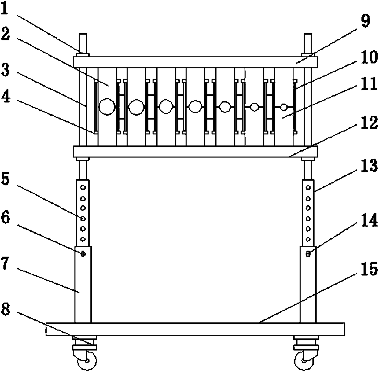
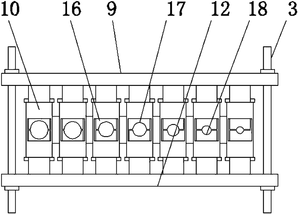
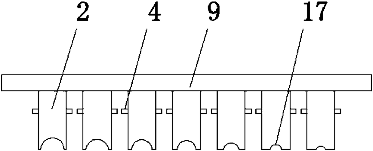
[0017] see Figure 1-5 , an embodiment provided by the present invention: a clamping device for textile yarns, comprising an upper pressing wheel 2, a sleeve 10, a lower pressing wheel 11 and a bottom plate 15, four corners of the bottom end of the bottom plate 15 are fixed with rollers 8 , and both ends of the top of the bottom plate 15 are fixed with a first support rod 7, the top of one side of the first support rod 7 is provided with a second screw hole 6,...


PUM


Abstract

The invention discloses a clamping device for textile yarn. The clamping device comprises upper clamping wheels, external members, lower pressing plates and a bottom plate. Rollers are fixed to the four corners of the bottom end of the bottom plate, first supporting rods are fixed to the two ends of the top of the bottom plate, second screw holes are formed in the top ends of one sides of the first supporting rods, fixing bolts are fixed into the second screw holes, second supporting rods are fixed into the first supporting rods, the lower pressing wheels corresponding to the upper pressing wheels are evenly fixed to the top end of a lower cross plate, lower grooves matched with upper grooves are formed in the top ends of the lower pressing wheels, the external members are arranged on theouter sides of the lower pressing wheels, and reserved holes are formed in the two sides of the external members. Through the arrangement of the first screws, the second screw holes and the fixing bolts, the second supporting rods can be conveniently adjusted to move on the first supporting rods, and therefore the height of the device is convenient and rapid to adjust.

Description

technical field [0001] The invention relates to the technical field of textile electromechanical equipment, in particular to a clamping device for textile yarns. Background technique [0002] With the continuous development of society and the continuous progress of the textile industry, all kinds of textile equipment are constantly being innovated. Take the textile machine as an example, and the yarn gripper is an important part of the textile machine. Such devices on the market today There are many types, which can basically meet people's needs, but there are still some problems. The traditional yarn clamp usually applies mechanical pressure to the two clamp arms to deform them and have left and right stress, so that the gap between the clamp heads The spacing becomes smaller, but in the rapid repetitive work of the loom, the clamp arm of the yarn clamp needs to be deformed and restored continuously. After a long time, the clamp arm will lose its elasticity, resulting in do...

Claims


Application Information

Patent Timeline
Patent Type & Authority Applications(China)
IPC IPC(8): D03D49/04
CPCD03D49/04
Inventor 牛利荣
Owner YANCHENG JUNLONG YARN CO LTD
Why Eureka
Try Eureka