Fireproof glass wall

A technology of fire-resistant glass and glass plate, which is applied in the direction of fire prevention and building components, etc. It can solve the problems of inconvenient installation of fire-proof glass and fire-proof rubber strips, unattractive appearance, poor mechanical properties, etc., and achieves simple structure, simple and convenient installation, and bearing good performance

Pending Publication Date: 2018-08-28
HUNAN GOLDWELL NEW MATERIALS TECH CO LTD
View PDF0 Cites 0 Cited by
  • Summary
  • Abstract
  • Description
  • Claims
  • Application Information

AI Technical Summary

Problems solved by technology

[0002] In the existing fire-resistant glass walls and partitions, the columns are all in the form of light-gauge steel or all in the form of full-heavy steel. Among them, the fire-resistant glass walls and partitions in the form of full-heavy steel for the columns are better in force, but the appearance is not beautiful enough, and the fire-resi

Method used


Image

  • Fireproof glass wall
  • Fireproof glass wall
  • Fireproof glass wall

Examples


Example Embodiment

[0040] Example 1:

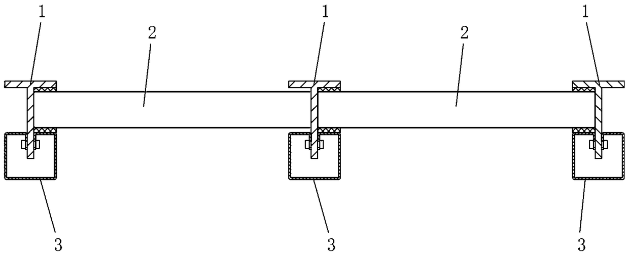
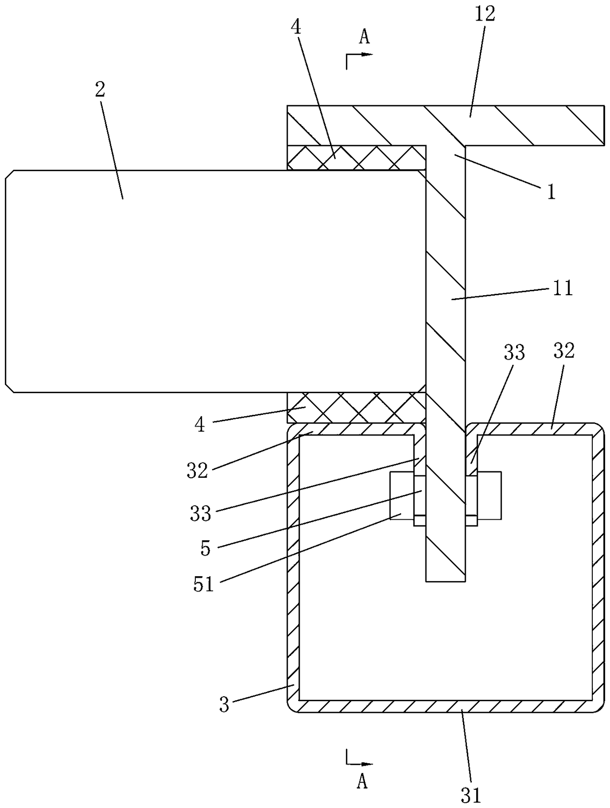
[0041] like Figure 1 to Figure 4 As shown, the fire-resistant glass wall of this embodiment includes a number of columns 1 arranged at intervals, and glass plates 2 are installed between two adjacent columns 1. The columns 1 are solid steel columns, and the columns 1 include trunks 11 connected as a whole. and side baffles 12, the glass plate 2 is placed between the trunks 11 of two adjacent uprights 1, and each upright 1 is connected with a detachable connecting assembly to press and fix the glass plate 2 on the side baffles 12. The first fireproof filler 4 is equally pressed between the pressing part 3 , the side block 12 and the glass plate 2 and between the pressing part 3 and the glass plate 2 . The column 1 of the fire-resistant glass wall adopts a solid steel column (heavy steel), and the glass plate 2 is pressed and fixed on the side block 12 of the column 1 by using the pressing part 3. The column 1 is the main force-bearing part, and its strengt...

Example Embodiment

[0051] Example 2:

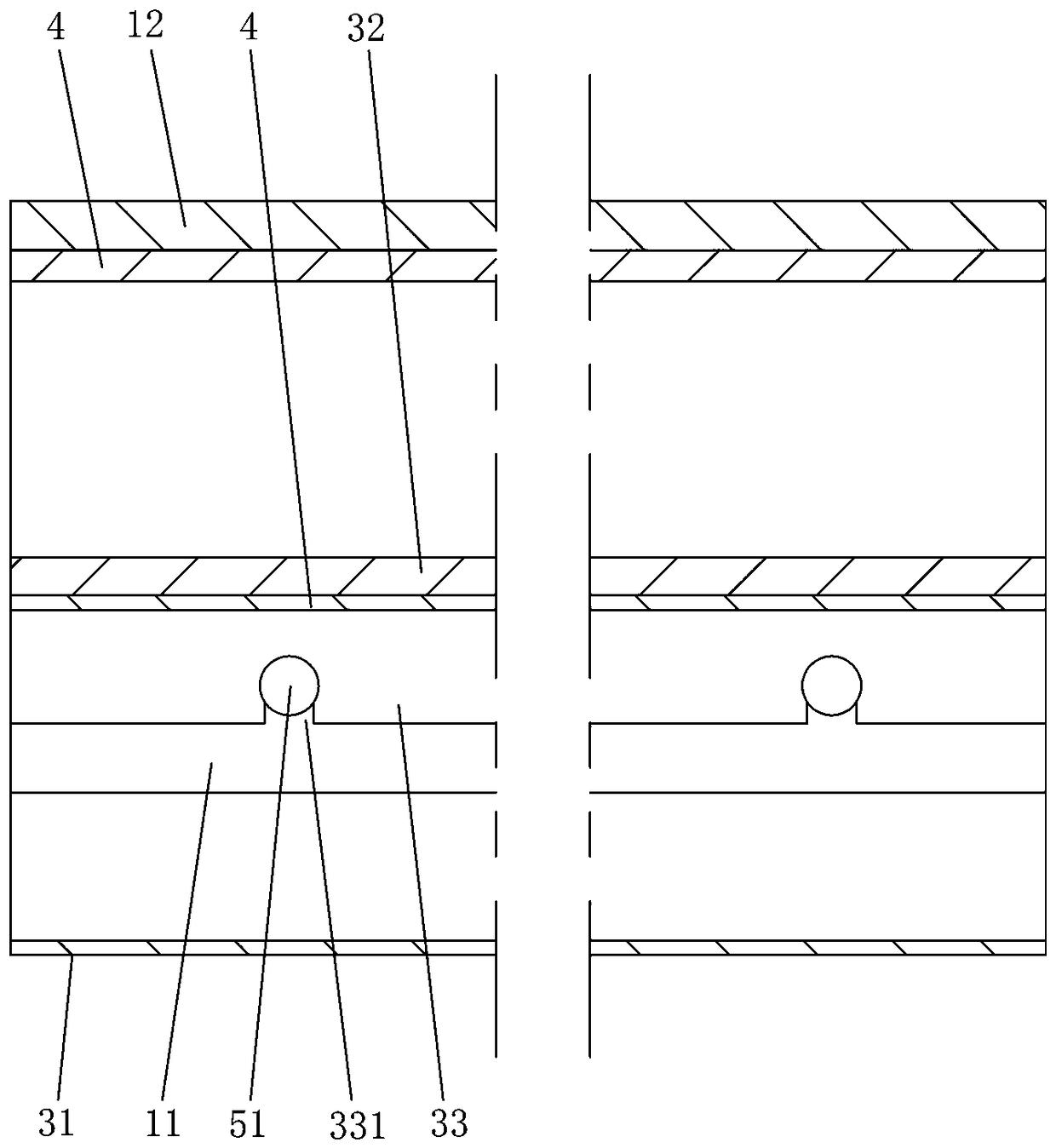
[0052] The fireproof glass wall of this embodiment is basically the same as that of Embodiment 1, the main difference is that, as Figure 5 and Image 6 As shown, in this embodiment, the two anti-retraction parts 5 are connected as one piece, which is a bent sheet material, which is U-shaped as a whole, including a bottom plate and two side plates connected to both sides of the bottom plate, The bottom plate is fixedly connected to the main body 11 , and the two side plates are respectively located on both sides of the main body 11 as the limiting parts 33 . In addition, in this embodiment, each limiting portion 33 is not provided with a bayonet 331 . In this embodiment, the two backstopping parts 5 are connected into one piece, which is convenient to manufacture and install, and low in cost.

Example Embodiment

[0053] Example 3:

[0054] The fireproof glass wall of this embodiment is basically the same as that of Embodiment 1, the main difference is that, as Figure 7 As shown, in this embodiment, the two anti-retraction parts 5 are respectively threaded on the main body 11, which is convenient for disassembly and assembly. In addition, in this embodiment, each limiting portion 33 is not provided with a bayonet 331 .

[0055] In this embodiment, a second fireproof filler 9 is provided between each column 1 and the glass plate 2 , which can further improve the fireproof sealing performance and avoid rigid contact between the column 1 and the glass plate 2 .


PUM


Abstract

The invention discloses a fireproof glass wall. The fireproof glass wall comprises a plurality of vertical columns, wherein the vertical columns are arranged at intervals. Glass plates are installed between every two adjacent vertical columns. Each vertical column is a solid steel column. The vertical columns comprise main body parts and side blocking parts, wherein the main body parts and the side blocking parts are connected as a whole. The glass plates are arranged on the main body parts between every two adjacent vertical columns. Pressing parts capable of pressing and fixing the glass plates on the side blocking parts are connected to the vertical columns through detachable connecting assemblies. First fireproof filling pieces are arranged between the glass plates and the vertical columns and/or between the glass plates and the pressing parts. The firewall glass wall has the advantages of simple structure, low cost, simple and convenient installation, good stability and aesthetics.

Description

technical field [0001] The invention relates to the technical field of firewalls, in particular to a fireproof glass wall. Background technique [0002] In the existing fire-resistant glass walls and partitions, the columns are all in the form of light-gauge steel or all in the form of full-heavy steel. Among them, the fire-resistant glass walls and partitions in the form of full-heavy steel for the columns are better in force, but the appearance is not beautiful enough, and the fire-resistant glass And the shortcomings of inconvenient installation of fire-resistant rubber strips. The fire-resistant glass walls and partitions in the form of all-light steel for the columns have a beautiful appearance, but there are problems of poor mechanical properties and high costs, and large sizes need to be used to meet the strength design requirements. Contents of the invention [0003] The technical problem to be solved by the present invention is to overcome the deficiencies of the ...

Claims


Application Information

Patent Timeline
IPC IPC(8): E04B1/94
CPCE04B1/94
Inventor 李杰谢斌泉其他发明人请求不公开姓名
Owner HUNAN GOLDWELL NEW MATERIALS TECH CO LTD
Why Eureka
Try Eureka