Rapid detection device and detection method for track plate deformation

A detection device and detection method technology, applied in the direction of measurement device, optical device, instrument, etc., can solve the problems of high cost, long time, complicated workload of inspection personnel, etc., and achieve the effect of improving accuracy and saving cost

Pending Publication Date: 2018-08-28
CHINA RAILWAY 19 BUREAU GRP CO LTD +2
View PDF0 Cites 6 Cited by
  • Summary
  • Abstract
  • Description
  • Claims
  • Application Information

AI Technical Summary

Problems solved by technology

Due to the high accuracy requirements of track slab detection, two methods are currently used to control the accuracy of CRTS III track slabs. One is three-dimensional laser scanning; the other is total station with frame measurement. The above two methods are generally expensive. , numerous procedures, complicated technology, and great impact on the environment, which requires careful implementation by a professional team
In particular, the total station combined with the frame measurement method not only occupies special equipment, but also needs to use the total station to freely build a station when testing CRTS III track slabs. The complex construction site environment and personnel are more difficult for CRTS III track slab testing. And it takes a long time, resulting in low accuracy of the test results, and the workload of the testers is also very complicated

Method used


Image

  • Rapid detection device and detection method for track plate deformation
  • Rapid detection device and detection method for track plate deformation
  • Rapid detection device and detection method for track plate deformation

Examples


Embodiment

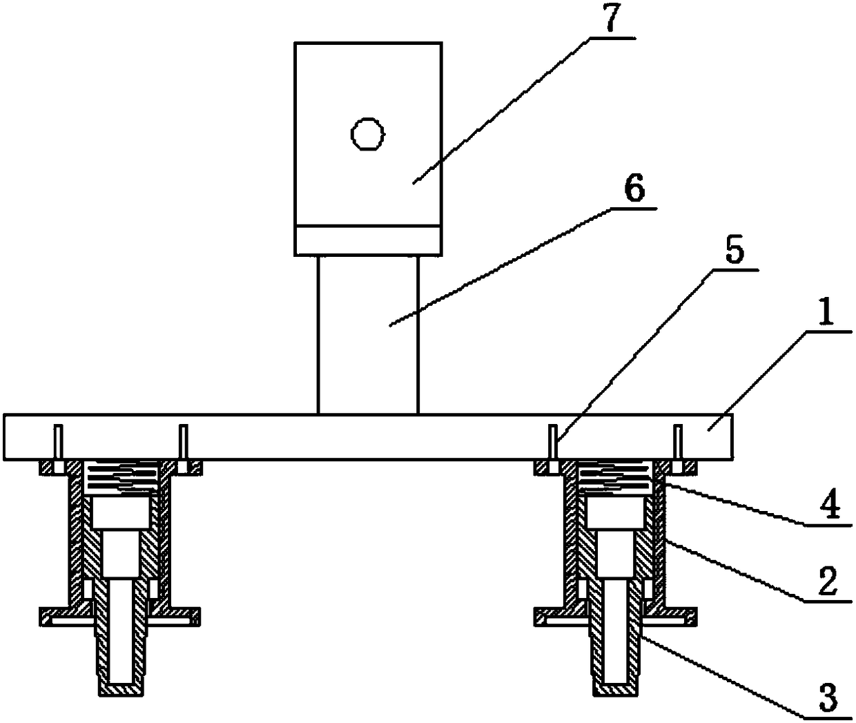
[0040] 1. Place the inventive equipment on the head and tail rail grooves on one side of the CRTS III track plate, and put the figure 1 Put the telescopic foot 3 in the CRTS III type plate screw inspection hole, rely on the tension spring 4 to ensure that the telescopic foot 3 is closely attached to the inner diameter of the CRTS III type plate screw inspection hole, and at the same time check the support sleeve 2 and the CRTS III type track plate bearing The rail grooves are in tight contact.

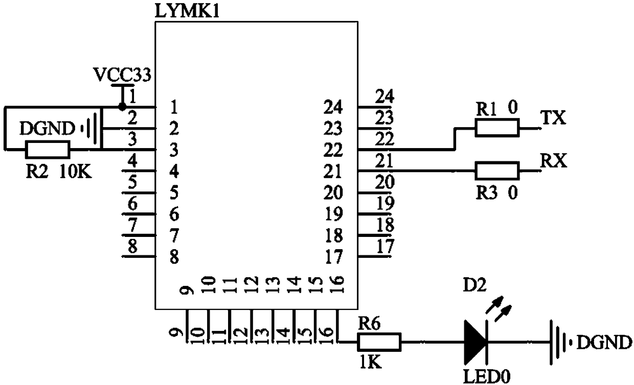
[0041] 2. Considering the possible work difference in the production process of CRTS III type track slab rail bearing groove, it is necessary to use figure 2 Adjust the X-direction adjustment knob 9 and the Y-direction adjustment knob 10 shown in , and fine-tune the laser emitted by the laser emitting component, so that the value displayed on the measurement terminal is close to 0 (X and Y). At this time, the laser emitted from the laser emitting component Laser rays, which can mea...


PUM


Abstract

The invention discloses a rapid detection device and a detection method for track plate deformation. The device comprises a beam, a support sleeve, a telescopic leg, a tension spring, a fixing bolt, abracket, and a PSD laser system, wherein the telescopic leg is located in the support sleeve, and the lower end of the telescopic leg is exposed outside the support sleeve; the upper end of the support sleeve is fixedly connected with the lower end surface of the beam through the fixing bolt; the tension spring is arranged between the beam and the upper end of the telescopic leg; the upper end ofthe beam is provided with the bracket; the bracket is provided with the PSD laser system; the PSD laser system is wirelessly connected with a detection system. Compared with the prior art, the rapiddetection device and the detection method for the track plate deformation have the advantages that deformation detection is performed on a CRTS III type track plate, the accuracy is improved and the requirements on the field environment, personnel and equipment are reduced compared with the conventional on-site detection; the measurement method is rapider, more accurate and more cost effective than the existing measurement method.

Description

technical field [0001] The invention relates to the application field of sensor technology in the construction of ballastless track of high-speed railway, in particular to a rapid detection device and detection method for track plate deformation. Background technique [0002] CRTSⅢ type slab ballastless track is a ballastless track with completely independent intellectual property rights based on the introduction, absorption and re-innovation in my country. It has the characteristics of high precision, two-way prestressing, simple process, and factory production. However, like the foreign Borg slab (called CRTS II track slab in China), due to the long and thin concrete structure, the track slab is prone to warping and deformation during transportation, storage and hoisting due to the influence of the concrete's own stress and gravity. When the deformation value is greater than the project expectation, it will affect the construction quality of the track. Therefore, detecting...

Claims


Application Information

Patent Timeline
Patent Type & Authority Applications(China)
IPC IPC(8): G01B11/16
CPCG01B11/16
Inventor 高俊贾宝红丁伟张晓峰温永达邱志海聂磊陈伟曹明春邹德征
Owner CHINA RAILWAY 19 BUREAU GRP CO LTD
Why Eureka
Try Eureka