Control system in damping bridge

A control system and central control module technology, applied in the field of bridge shock absorption, can solve problems such as inaccurate detection and quantification, difficult safety assessment, and reduced bridge safety

Inactive Publication Date: 2018-08-28
于军辉
View PDF7 Cites 2 Cited by
  • Summary
  • Abstract
  • Description
  • Claims
  • Application Information

AI Technical Summary

Problems solved by technology

[0005] The data processing speed of the control system in the existing shock-absorbing bridge is slow, which greatly affects the monitoring of bridge vibration data, resulting in a greatly reduced bridge safety; at the same time, the monitoring data is judged by humans, which is subjective and inaccurate
[0006] In the process of safety evaluation of seismic-absorbing bridges, there are many factors that affect its safety performance. Some factors can be quantified, while some factors can only be analyzed qualitatively. There are correlations between various factors and affect the safety of seismic-absorbing bridges. The main factor is the defect, the detection process is very complicated, and the quantitative results are not accurate, these situations bring great difficulties and doubts to its safety assessment
The current safety assessment of shock-absorbing bridges mostly adopts a single-angle evaluation method, and draws a conclusion from the theoretical aspect whether the shock-absorbing bridge can work safely, and cannot comprehensively solve the problem of its safety degree
The specific analysis is as follows: the detection and quantification of defects are inaccurate; the single-angle evaluation method relies too much on field data, and cannot comprehensively consider all the main factors affecting the safety of seismic bridges, and clarify the relationship between each impact and the actual situation Inconsistent; the result of the assessment is only a theoretical conclusion on whether it can work safely, and it cannot solve the problem of safety level, let alone dynamically monitor the changing trend of disasters, so as to better and more accurately detect disasters in time and prevent them in advance
The above problems will make the safety assessment result unsatisfactory, and the result is often: the theoretical result of the assessment is still within the safety permit, but in fact the shock-absorbing bridge has failed and cannot be used

Method used


Image

  • Control system in damping bridge
  • Control system in damping bridge
  • Control system in damping bridge

Examples


Embodiment Construction

[0130] In order to further understand the content, features and effects of the present invention, the following examples are given, and detailed descriptions are given below with reference to the accompanying drawings.

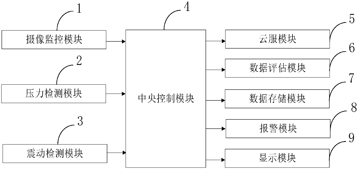
[0131] Such as figure 1 As shown, the control system in the damping bridge provided by the present invention includes: camera monitoring module 1, pressure detection module 2, vibration detection module 3, central control module 4, cloud service module 5, data evaluation module 6, data storage module 7 , an alarm module 8, and a display module 9.

[0132] The camera monitoring module 1 is connected with the central control module 4, and is used to monitor the bridge in real time through the camera;

[0133] The pressure detection module 2 is connected with the central control module 4, and is used to detect the pressure on the bridge surface in real time through the pressure sensor arranged on the bridge surface;

[0134] The vibration detection module 3 is...


PUM


Abstract

The present invention belongs to the technical field of bridge damping, and discloses a control system in a damping bridge. The control system comprises a camera monitoring module, a pressure detection module, a vibration detection module, a central control module, a cloud service module, a data assessment module, a data storage module, an alarm module and a display module. The control system employs the cloud service module to greatly improve the speed for analysis and processing of the bridge vibration monitoring data and improve the monitoring efficiency; and moreover, the control system employs the data assessment module to perform mathematical statistics of detection data and make scientific and accurate determination so as to avoid generation of a condition that data processing is not accurate caused by man-made subjective factors.

Description

technical field [0001] The invention belongs to the technical field of bridge damping, in particular to a control system in a damping bridge. Background technique [0002] Bridges generally refer to structures erected on rivers, lakes and seas to allow vehicles and pedestrians to pass smoothly. In order to adapt to the modern high-speed development of the transportation industry, bridges are also extended to buildings that cross mountain streams, poor geology or meet other transportation needs to make traffic more convenient. A bridge is generally composed of a superstructure, a substructure, a support and ancillary structures. The superstructure is also called a bridge span structure, which is the main structure for crossing obstacles; the substructure includes abutments, piers and foundations; Or the force transmission device installed at the supporting place of the bridge abutment; the auxiliary structures refer to the bridge head board, conical slope protection, bank pr...

Claims


Application Information

Patent Timeline
Patent Type & Authority Applications(China)
IPC IPC(8): G01D21/02G01N27/85G05B19/04
CPCG01D21/02G01N27/85G05B19/04
Inventor 王小雨宋高峰于军辉
Owner 于军辉
Why Eureka
Try Eureka