Assembly method of circuit breaker

An assembly method and technology of circuit breakers, which are applied in the manufacture of circuits, emergency protection devices, emergency protection devices, etc., can solve the problems of many artificial assembly problems, difficult assembly, and many parts of circuit breakers, and achieve the difficulty of installation operation and low accuracy requirements , Improve stability and accuracy consistency, compact and stable assembly effect

Active Publication Date: 2020-06-30
ZHEJIANG CHINT ELECTRIC CO LTD
View PDF5 Cites 0 Cited by
  • Summary
  • Abstract
  • Description
  • Claims
  • Application Information

AI Technical Summary

Problems solved by technology

[0003] In recent years, domestic labor costs have risen, and the assembly cost of circuit breaker assemblers has increased significantly
The existing circuit breaker has many parts, it is difficult to assemble, and it is not easy to realize automatic assembly, which leads to high assembly cost of the circuit breaker. At the same time, there are many problems in manual assembly
In addition, the operating mechanism of the circuit breaker needs to assemble many parts, and the connection structure between the parts is relatively complicated, so the production efficiency of the manual assembly process is low, the product consistency is poor, and the complex connection relationship between parts is also difficult. It is impossible to realize the automatic assembly of the operating mechanism through the equipment

Method used


Image

  • Assembly method of circuit breaker
  • Assembly method of circuit breaker
  • Assembly method of circuit breaker

Examples


Embodiment Construction

[0037] The following is attached Figures 1 to 10 The given examples further illustrate the specific implementation of the circuit breaker and its assembly method of the present invention. The circuit breaker and its assembly method of the present invention are not limited to the description of the following embodiments.

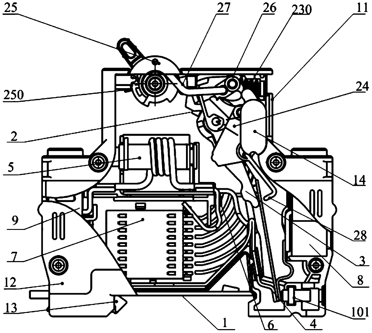
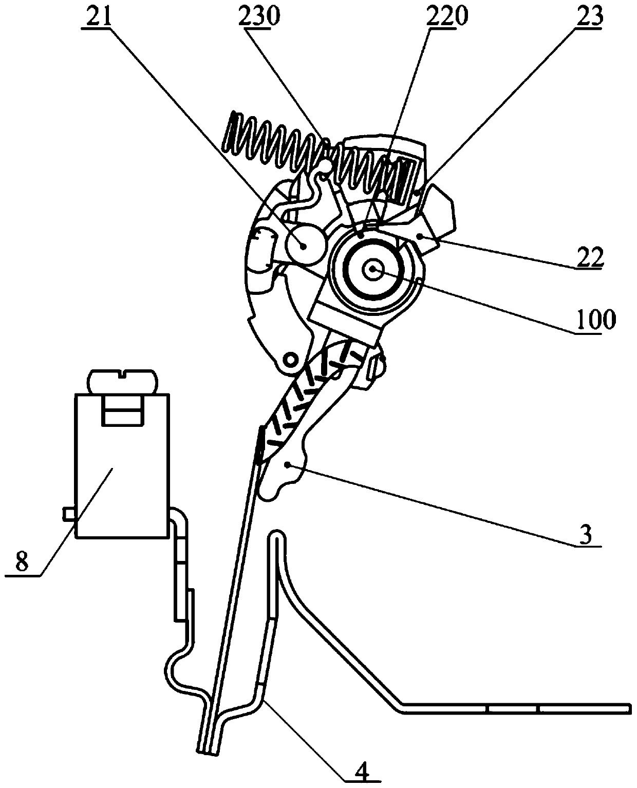
[0038] Such as figure 1 and figure 2 As shown, the circuit breaker of the present invention includes a housing 1, an operating mechanism 2 installed in the housing 1, a moving contact 3, a thermal system 4, a magnetic system 5, a static contact 6, an arc extinguishing chamber 7, a second A connection terminal 8 and a second connection terminal 9, the housing 1 includes a base 11, an upper cover 12, a stopper 13 and a cover plug 14, the upper cover 12 can be fastened and installed on the base 11; the operating mechanism 2 It includes a handle 25 , a U-shaped rod 27 , a connecting rod 26 , a limiting piece 21 , a lever 23 , a contact support 22 , a lock ca...


PUM


Abstract

Provided is a circuit breaker, which comprises a housing, and an operating mechanism, a moving contact, a thermal system, a magnetic system, a fixed contact and an arc extinguish chamber, which are arranged in the housing. The assembly method of the circuit breaker comprises the following steps: sleeving a contact support of the circuit breaker, the moving contact and a lever on a mechanism rotating shaft in sequence, and enabling a lock to be rotatably arranged on the lever to form a stacked structure; installing the stacked structure in a base of the housing, vertically fixing the mechanismrotating shaft 100 on a bottom plate of the base, and arranging the contact support between the moving contact and the bottom plate; rotatably arranging a connecting rod on the lever, wherein one endof the connecting rod is arranged opposite to the lock; installing a handle in the base; inserting the two ends of a U-shaped rod into a first rod hole of the handle and a second rod hole of the connecting rod; and buckling the upper cover of the housing on the base, wherein the step d) can be before the step c) or after the step c) and before the step e). The invention provides the circuit breaker, which is simple in structure, high in assembling efficiency and high in product consistency, and the assembly method thereof.

Description

technical field [0001] The invention relates to the field of low-voltage electrical appliances, in particular to a circuit breaker and an assembly method thereof. Background technique [0002] Circuit breakers utilize various mechanism unlocking methods to detect faults and open circuits affected by them. The unlocking device includes a sensor and activates a mechanism of the circuit breaker which, upon detection of a fault, disengages the movable contact from the fixed contact. One type of trip device used in circuit breakers is the electromagnetic trip device, which is commonly used to open a circuit breaker during an emergency. An example of an electromagnetic trip device is a solenoid connected in series to the wires of the circuit breaker and arranged to activate the operating mechanism when the current in the wires exceeds a predetermined level. Another type of trip device used in circuit breakers is a thermal trip device, which is commonly used to open a circuit bre...

Claims


Application Information

Patent Timeline
Patent Type & Authority Patents(China)
IPC IPC(8): H01H71/40H01H69/00
CPCH01H69/00H01H71/40
Inventor 张人旭司莺歌
Owner ZHEJIANG CHINT ELECTRIC CO LTD
Why Eureka
Try Eureka