Direct-drive gun turret rotating device of frame-free combined type permanent magnet synchronous motor
A technology for permanent magnet synchronous motors and rotating devices, which is applied to synchronous motors, electromechanical devices, turrets, etc. with stationary armatures and rotating magnets. Cost, high control accuracy, and the effect of improving drive efficiency
- Summary
- Abstract
- Description
- Claims
- Application Information
AI Technical Summary
Problems solved by technology
Method used
Image

Examples
Embodiment 1
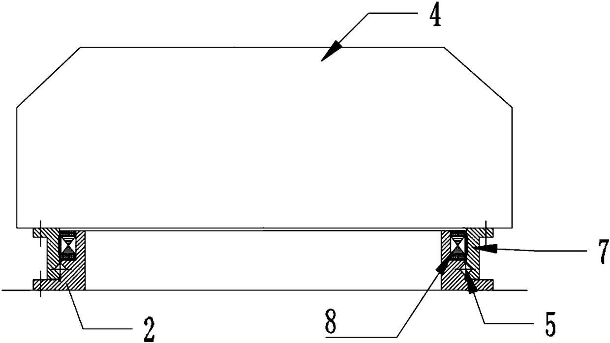
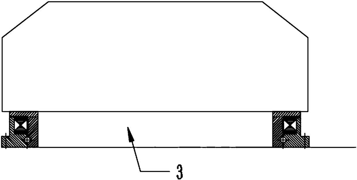
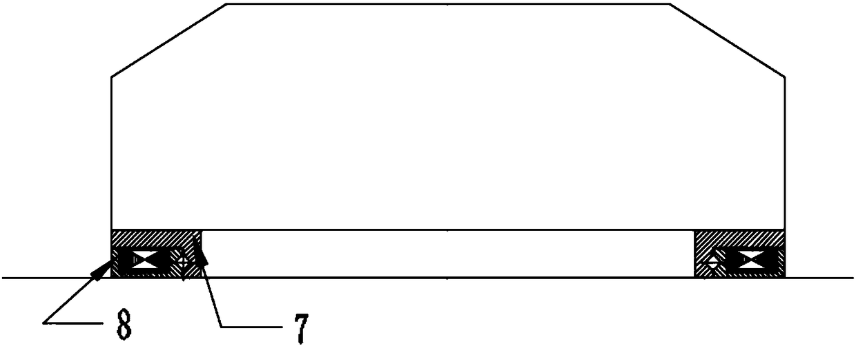
[0033] Such as Figure 1~5As shown, this embodiment provides a frameless combined permanent magnet synchronous motor direct-driven turret rotating device, including a fixed base 1, a turret driving rotary table 4 and a driving device; the fixed base 1 is used to carry the The turret drives the rotary table 4, and the driving device provides power for the turret driving rotary table 4; the driving device is a frameless combined permanent magnet synchronous motor 2, including a rotor assembly 7 and a stator assembly 8; wherein, the The stator assembly 8 is opposite to the rotor assembly 7 and a slewing bearing is provided between the stator assembly 8 and the rotor assembly 7, and the slewing bearing is a cross roller bearing 5; the stator assembly 8 provides a rotating magnetic field Drive the rotor assembly 7 to rotate; the stator assembly 8 is fixedly connected to the fixed base 1, and the rotor assembly 7 is fixedly connected to the turret driving rotary table 4; the stator ...
Embodiment 2
[0040] Such as Figure 6~7 As shown, the preferred embodiment of the present invention is to provide a frameless combined permanent magnet synchronous motor direct-driven turret rotating device, the structure and working principle of this embodiment are similar to that of embodiment 1, but different from embodiment 1 The difference is that the rotor assembly in this embodiment further includes pressure plates 73 distributed in the axial and / or circumferential directions of the rotor base 71, and the magnetic steel substrate 72 is arranged on the pressure plates 73 and the rotor base. 71; the inner cavity of the pressure plate 73 is provided with the magnetic steel substrate 72, and the edge of the pressure plate 73 is provided with a second flange structure 74, and the second flange structure 74 is matched with the rotor base 71 Evenly distributed positioning holes are provided, and the positioning holes are used to fix the magnetic steel substrate 72 embedded in the pressing ...
Embodiment 3
[0042] Such as Figure 8 As shown, the preferred embodiment of the present invention is to provide that this embodiment is similar in structure and working principle to Embodiment 1 or 2, and the difference from Embodiment 1 or 2 is that the stator assembly 8 in this embodiment There is also a cooling device; the cooling device includes a cooling water pipe 9 annularly arranged on the stator core, and / or a cooling air duct 10 on the stator base, and the direction of the cooling air duct 10 is the same as The plane of rotation of the rotor assembly 7 is vertical. The stator assembly 8 generates a rotating magnetic field and drives the rotation of the rotor assembly 7, which will generate a large amount of heat and affect the normal operation of the equipment. The circulating water in the cooling water pipe 9 will take out the heat generated by the equipment in time, Secondly, the cooling air duct 10 can also take away part of the heat, assisting in strengthening the heat dissi...
PUM
 Abstract
Description
Claims
Application Information
 - R&D Engineer
- R&D Manager
- IP Professional
- Industry Leading Data Capabilities
- Powerful AI technology
- Patent DNA Extraction
Browse by: Latest US Patents, China's latest patents, Technical Efficacy Thesaurus, Application Domain, Technology Topic.
© 2024 PatSnap. All rights reserved.Legal|Privacy policy|Modern Slavery Act Transparency Statement|Sitemap