Robot joint rotating device directly driven by frameless type permanent magnet synchronous motor

A technology of permanent magnet synchronous motors and robot joints, which is applied in the direction of electromechanical devices, manipulators, electrical components, etc., can solve problems such as bloated robot joints, achieve simplified driving methods and equipment structures, reduce volume, and meet flexible selection requirements Effect

Pending Publication Date: 2018-07-06
HUBEI HUANYEE ELECTROMAGNETIC EQUIP ENG TECH CO LTD
View PDF6 Cites 0 Cited by
  • Summary
  • Abstract
  • Description
  • Claims
  • Application Information

AI Technical Summary

Problems solved by technology

[0003] Traditional robots can clearly see the servo motors leaking out of their joints. In addition to the motors we can see, there are also very complicated reducers and brake mechanisms in these joints, making the joints of the robot become very bloated

Method used


Image

  • Robot joint rotating device directly driven by frameless type permanent magnet synchronous motor
  • Robot joint rotating device directly driven by frameless type permanent magnet synchronous motor
  • Robot joint rotating device directly driven by frameless type permanent magnet synchronous motor

Examples


Embodiment 1

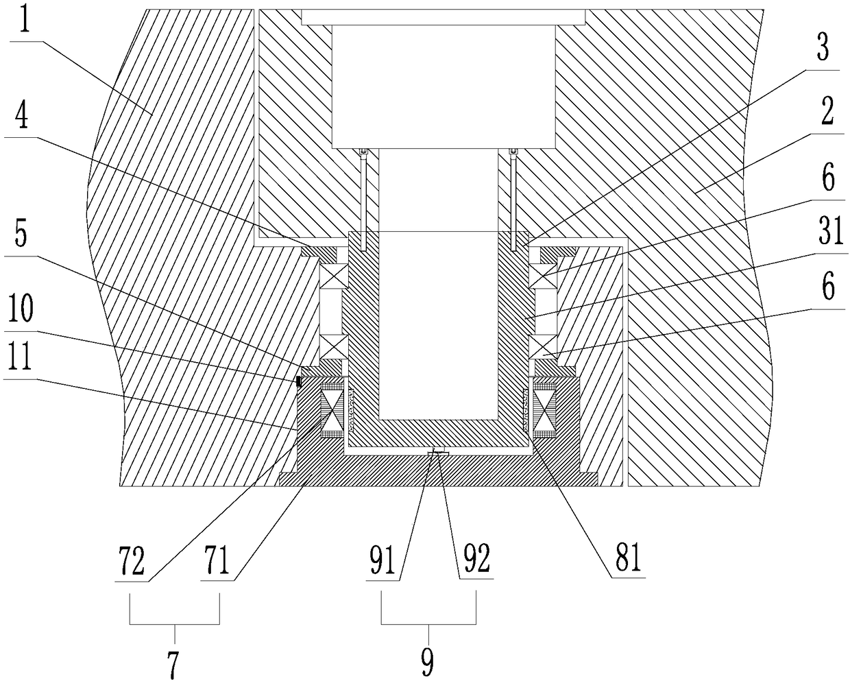
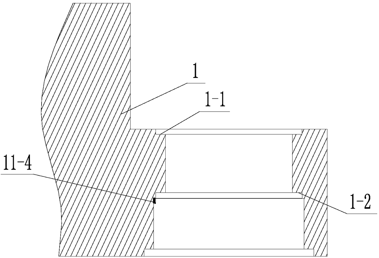
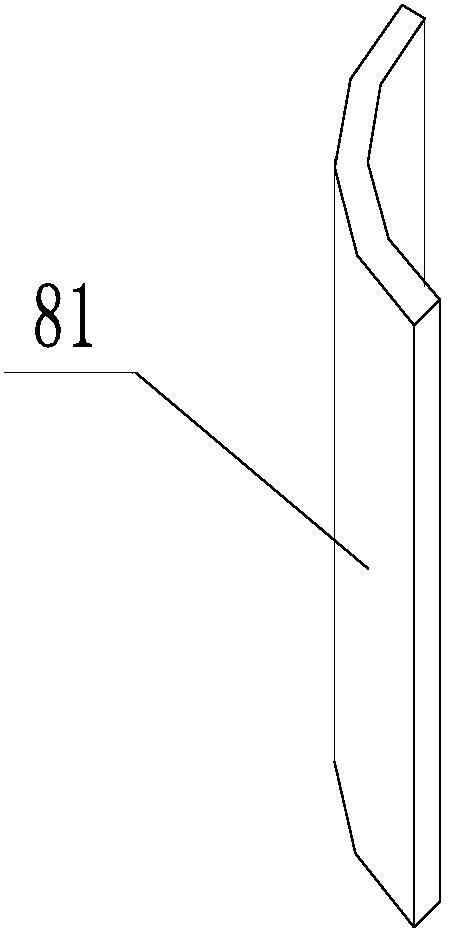
[0029] Such as Figure 1-5 As shown, a frameless permanent magnet synchronous motor direct-driven robot joint rotation device, the robot joint rotation device includes a forearm 1, a rotating shaft 3 and a rear arm 2; the end of the forearm 1 is provided with a mounting hole 11; The rotating shaft 3 is installed in the mounting hole 11 through the bearing 6; the rear arm 2 is connected with the rotating shaft 3, and rotates around the forearm 1 through the rotating shaft 3; the rotating shaft 3 is made of frameless The permanent magnet synchronous motor is directly driven; the frameless permanent magnet synchronous motor includes a stator assembly 7 and a rotor assembly 8; the stator assembly 7 is fixed on the base of the forearm 1 to provide a rotating magnetic field for the rotor assembly 8; it has a permanent magnet The characteristic rotor assembly 8 is fixedly mounted on the rotating shaft 3;

[0030] Wherein, the stator assembly 7 includes a stator core 1 72 and a stato...

Embodiment 2

[0034] Such as Figure 6-8As shown, a frameless permanent magnet synchronous motor direct-driven robot joint rotation device, the robot joint rotation device includes a forearm 1, a rotating shaft 3 and a rear arm 2; the end of the forearm 1 is provided with a mounting hole 11; The rotating shaft 3 is installed in the mounting hole 11 through the bearing 6; the rear arm 2 is connected with the rotating shaft 3, and rotates around the forearm 1 through the rotating shaft 3; the rotating shaft 3 is made of frameless The permanent magnet synchronous motor is directly driven; the frameless permanent magnet synchronous motor includes a stator assembly 7 and a rotor assembly 8; the stator assembly 7 is fixed on the base of the forearm 1 to provide a rotating magnetic field for the rotor assembly 8; it has a permanent magnet The characteristic rotor assembly 8 is fixedly mounted on the rotating shaft 3;

[0035] Wherein, the stator assembly 7 includes a second stator core 73 and a s...

Embodiment 3

[0039] Such as Figure 9 As shown, a frameless permanent magnet synchronous motor direct-driven robot joint rotation device, the robot joint rotation device includes a forearm 1, a rotating shaft 3 and a rear arm 2; the end of the forearm 1 is provided with a mounting hole 11; The rotating shaft 3 is installed in the mounting hole 11 through the bearing 6; the rear arm 2 is connected with the rotating shaft 3, and rotates around the forearm 1 through the rotating shaft 3; the rotating shaft 3 is made of frameless The permanent magnet synchronous motor is directly driven; the frameless permanent magnet synchronous motor includes a stator assembly 7 and a rotor assembly 8; the stator assembly 7 is fixed on the base of the forearm 1 to provide a rotating magnetic field for the rotor assembly 8; it has a permanent magnet The characteristic rotor assembly 8 is fixedly mounted on the rotating shaft 3;

[0040] Wherein, the stator assembly 7 includes stator core 1 72 and stator core...


PUM


Abstract

The invention discloses a robot joint rotating device directly driven by a frameless type permanent magnet synchronous motor. The robot joint rotating device comprises a front arm, a rotating shaft and a rear arm. A mounting hole is formed in the end of the front arm. The rotating shaft is installed in the mounting hole through a bearing. The rear arm is connected with the rotating shaft and rotates around the front arm through the rotating shaft. The robot joint rotating device directly driven by the frameless type permanent magnet synchronous motor is characterized in that the rotating shaftis directly driven by the frameless type permanent magnet synchronous motor. According to the robot joint rotating device directly driven by the frameless type permanent magnet synchronous motor, therobot joint rotating device is simple in structure, small in installation size and high in control precision.

Description

technical field [0001] The invention relates to the technical field of robot equipment, in particular to a robot joint rotation device directly driven by a frameless permanent magnet synchronous motor. Background technique [0002] With the development of modern technology, robots are playing an increasingly important role in all walks of life. As a relatively important part of robots, robot joint rotation devices have attracted more and more attention. [0003] Traditional robots can clearly see the servo motors leaking out of their joints. In addition to the motors we can see, there are also very complicated reducers and brake mechanisms in these joints, making the joints of the robot become extremely bloated. Of course for many large robots this is not a problem. But for those small robots that are being increasingly used in the market and around equipment, especially collaborative robots that need to cooperate with people to complete various complex auxiliary productio...

Claims


Application Information

Patent Timeline
Patent Type & Authority Applications(China)
IPC IPC(8): B25J17/02H02K7/14
CPCH02K7/14B25J17/0258
Inventor 黄诚杨勇强
Owner HUBEI HUANYEE ELECTROMAGNETIC EQUIP ENG TECH CO LTD
Why Eureka
Try Eureka