Lampholder threading assembling equipment

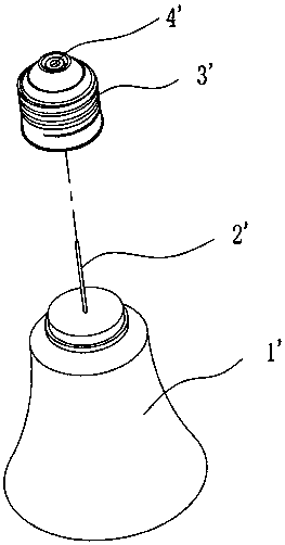
A technology for assembling equipment and lamp caps, which is applied in metal processing equipment, metal processing, manufacturing tools, etc., and can solve the problem that the wick 2' cannot maintain a vertical state, the lamp cap 3' cannot be automated, and the wick 2' is reserved long, etc. problem, achieve the effect of reducing labor intensity, simple structure, and improving yield rate

Pending Publication Date: 2018-08-31
厦门市先创鹭为自动化科技有限公司
View PDF7 Cites 0 Cited by
  • Summary
  • Abstract
  • Description
  • Claims
  • Application Information

AI Technical Summary

Problems solved by technology

[0002] like figure 1 As shown, the LED lamp includes a lamp cup 1', a wick 2' and a lamp cap 3'. During the assembly process, first install the wick 2' above the lamp cup 1', and then install the lamp cap 3'. It is necessary to pass through the round hole 4' above the lamp cap 3', and then rivet the lamp cap on the lamp cup. In the actual production process, because the round hole 4' on the lamp cap 3' is small, the wick 2' is reserved relatively long. The wick 2' cannot be kept vertical, and is usually twisted and deformed. The lamp cap 3' cannot be automatically threaded through the wick and assembled. Manual threading is required to press the lamp cap 3' on the lamp cup 1', and then perform automatic riveting

Method used


Image

  • Lampholder threading assembling equipment
  • Lampholder threading assembling equipment
  • Lampholder threading assembling equipment

Examples


Embodiment Construction

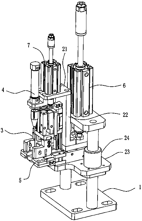
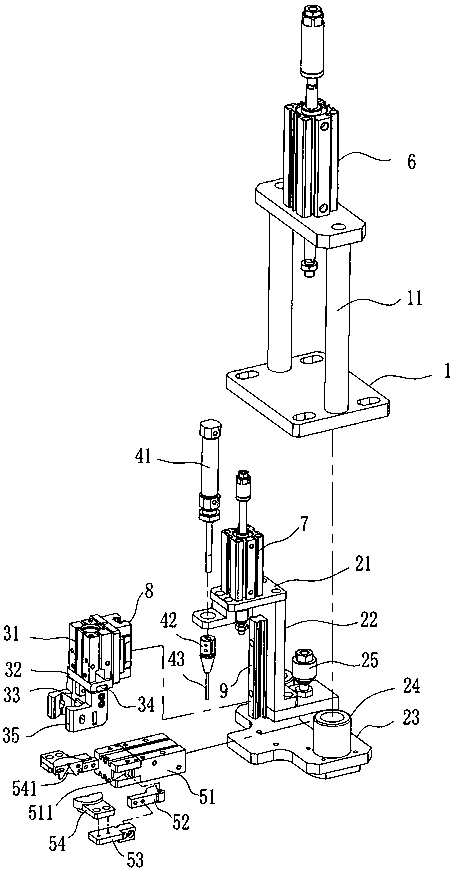
[0026] In order to enable those skilled in the art to better understand the technical solutions of the present invention, the present invention will be described in further detail below in conjunction with the accompanying drawings and specific embodiments.

[0027] Such as figure 2 As shown, the present invention discloses a lamp cap threading assembly device, which includes a frame 1 , a lamp pressing module 2 , a claw mechanism 3 , a wire fixing module 4 and a lamp cap releasing mechanism 5 . The main cylinder 6 is installed on the frame 1, and the lamp module 2 is movably installed on the frame 1. The lamp module 2 is connected with the main cylinder 6, and the main cylinder 6 drives the lamp module 2 to move up and down on the frame 1. . The lamp pressing module 2 is equipped with a pressing lamp cylinder 7, and the clamping claw mechanism 3 is used to clamp the lamp head 3′. The lamp module 2 side moves up and down. The wire fixing module 4 is installed on the pressi...


PUM


Abstract

The invention discloses lampholder threading assembling equipment which comprises a rack, a lamp pressing module, a clamping claw mechanism, a wire-fixing module and a lampholder placing mechanism, wherein a main air cylinder is mounted on the rack; the lamp pressing module is movably mounted on the rack and is connected to the main air cylinder; a lamp pressing air cylinder is mounted on the lamppressing module, and the clamping claw mechanism is movably mounted on the lamp pressing module; the wire-fixing module is mounted on the lamp pressing module, and is arranged above the clamping clawmechanism, and the wire-fixing module comprises a wire-fixing air cylinder, a hollow pipe sleeve and a hollow pipe; and the lamp holder placing mechanism arranged below the clamping claw mechanism comprises a rotary control air cylinder, two rotary arm assemblies and two lamp placing plates, wherein the rotary control air cylinder controls the two rotary arm assemblies to rotate; the lamp placingplate is fixedly connected to the rotary arm assemblies; threading grooves are formed in the two lamp placing plates, and are arranged right below the hollow tube. The lampholder threading assemblingequipment is simple in structure, and the lampholder can be threaded and assembled to a lamp cup automatically, so that the automatic level of an LED production line is improved, and the labor intensity of workers is alleviated.

Description

technical field [0001] The invention relates to the technical field of automatic assembly of LED lamps, in particular to a lamp cap threading assembly device. Background technique [0002] Such as figure 1 As shown, the LED lamp includes a lamp cup 1', a wick 2' and a lamp cap 3'. During the assembly process, first install the wick 2' above the lamp cup 1', and then install the lamp cap 3'. It is necessary to pass through the round hole 4' above the lamp cap 3', and then rivet the lamp cap on the lamp cup. In the actual production process, because the round hole 4' on the lamp cap 3' is small, the wick 2' is reserved relatively long. The wick 2' cannot be kept vertical, and is usually twisted and deformed. The lamp cap 3' cannot be automatically threaded through the wick and assembled. Manual threading is required to press the lamp cap 3' on the lamp cup 1', and then perform automatic riveting . Contents of the invention [0003] The object of the present invention is t...

Claims


Application Information

Patent Timeline
Patent Type & Authority Applications(China)
IPC IPC(8): B23P19/04
CPCB23P19/006B23P19/04
Inventor 卢铭烽
Owner 厦门市先创鹭为自动化科技有限公司
Why Eureka
Try Eureka