
System and method for processing steel wire rope components

A technology of wire rope assembly and processing system, applied in the direction of applying stable tension/pressure to test the strength of materials, can solve the problems of low operation safety performance, low production efficiency, safety accidents, etc., to liberate labor productivity, improve production efficiency and improve production efficiency. The effect of production quality and labor intensity reduction

Active Publication Date: 2016-11-30
CMCU ENG
View PDF6 Cites 0 Cited by
  • Summary
  • Abstract
  • Description
  • Claims
  • Application Information

AI Technical Summary

Problems solved by technology

The fixed-length cutting of the steel wire rope, the threading and riveting of the two-section screw of the steel wire rope, the sheathing and riveting of the connecting plate, the tensile test of each riveting position of the component, etc., the production efficiency of the whole process is low, and at the same time, the steel wire rope is soft. , when in the simple operation process, the operator holds the pierced component close to the riveting press for riveting, the operation safety performance is low, and safety accidents are prone to occur

Method used


Image

  • System and method for processing steel wire rope components
  • System and method for processing steel wire rope components
  • System and method for processing steel wire rope components

Examples


Embodiment Construction

[0035] The preferred embodiments of the present invention will be described in detail below in conjunction with the accompanying drawings; it should be understood that the preferred embodiments are only for illustrating the present invention, rather than limiting the protection scope of the present invention.

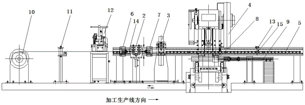
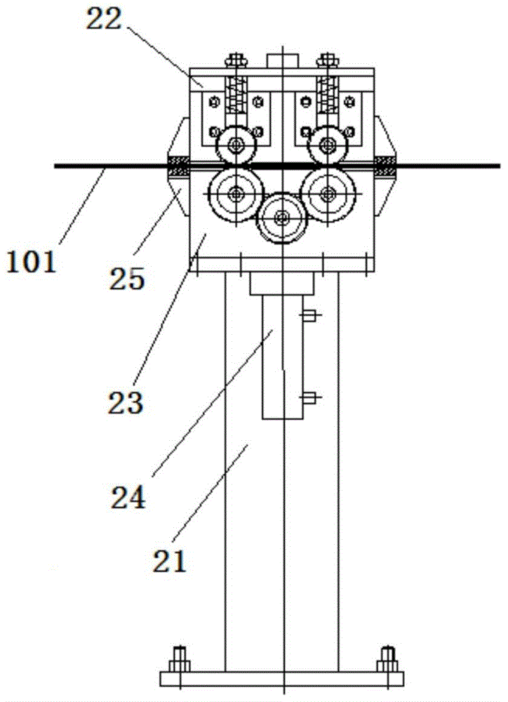
[0036] Such as figure 2 As shown, a steel wire rope assembly processing system, wherein, the steel wire rope assembly 1 includes a steel wire rope 101, a screw 102 arranged at both ends of the steel wire rope 101, and a connecting plate 103 arranged in the middle of the steel wire rope 101, and the processing system includes sequentially arranged for The feeding device 2 for pinching the steel wire rope 101, the first riveting press 3 for riveting the steel wire rope 101 and the screw 102, the second riveting press 4 for riveting the steel wire rope 101 and the connecting plate 103, and the connecting feeding device 2 , the production guide rail 5 of the first riveting...


PUM


Abstract

The invention discloses a steel wire rope assembly machining system and method and belongs to the technical field of factory automatic machining. A steel wire rope assembly comprises a steel wire rope, screws arranged at the two ends of the steel wire rope, and a connecting plate arranged in the middle of the steel wire rope. The machining system comprises a feeding device, a first riveting machine, a second riveting machine and a production guide rail, wherein the feeding device, the first riveting machine and the second riveting machine are arranged in sequence, and the production guide rail is used for connecting the feeding device, the first riveting machine and the second riveting machine. The feeding device and the first riveting machine are arranged on the same side of the second riveting machine. The machining system further comprises a first clamp, a second clamp and a third clamp. The first clamp and the second clamp are arranged on the production guide rail in a sliding manner and arranged on the two sides of the feeding device, and the third clamping device is arranged on the second riveting machine in a sliding manner. The machining system fills up the blank of domestic elevator production enterprises in the automatic machining industry of steel wire rope assemblies, formation of standardized production can be facilitated, and a systematic machining technology and a production system can be established.

Description

technical field [0001] The invention belongs to the technical field of factory automatic processing, and in particular relates to an automatic processing system and method for a steel wire rope assembly for opening and closing doors of an elevator, which are used to realize automatic processing and online detection of steel wire ropes, screw rods, and connecting plates. Background technique [0002] In the elevator manufacturing industry, the steel wire rope components used in the elevator switch door, its processing content includes: the threading of the two ends of the steel wire rope and the inner hole of the screw; the riveting of the threaded section of the screw after threading; Pressing; for the finished components, the stability of the connecting plate, screw and steel wire rope after riveting is checked by a tensile test. After processing, the component diagram is as follows figure 1 ,That figure 1 The position indicated by the middle arrow is the part that needs ...

Claims


Application Information

Patent Timeline
Patent Type & Authority Patents(China)
IPC IPC(8): B21F15/00B21F23/00G01N3/08
Inventor 巫江李宏李惕新杨亮孟令宽王佳
Owner CMCU ENG
Learn More