
Automatic clamping device for liner tube in PCVD equipment

An automatic clamping and lining technology, applied in glass manufacturing equipment, manufacturing tools, etc., can solve the problems of low work efficiency, poor sealing performance of a single O-ring, leakage of working gas, etc., to achieve convenient operation, good sealing, Improve the effect of wildcarding

Active Publication Date: 2018-08-31
YANGTZE OPTICAL FIBRE & CABLE CO LTD
View PDF8 Cites 3 Cited by
  • Summary
  • Abstract
  • Description
  • Claims
  • Application Information

AI Technical Summary

Problems solved by technology

[0003] 1. There are many types of liners, and liners with different specifications and outer diameters need to be matched with O-rings and lock nuts of different specifications;
[0004] 2. The sealing performance of a single O-ring is poor, and there is a risk of working gas leakage;
[0005] 3. Most of the installation and disassembly of the liner is to manually lock and disassemble the lock nut, and the work efficiency is low

Method used


Image

  • Automatic clamping device for liner tube in PCVD equipment
  • Automatic clamping device for liner tube in PCVD equipment
  • Automatic clamping device for liner tube in PCVD equipment

Examples


Embodiment Construction

[0027] It should be understood that the specific embodiments described here are only used to explain the present invention, not to limit the present invention.

[0028] It should be noted that, in the description of the present invention, the terms "horizontal", "vertical", "upper", "lower", "front", "rear", "left", "right", "vertical", The orientation or positional relationship indicated by "horizontal", "top", "bottom", "inner", "outer", etc. is based on the orientation or positional relationship shown in the drawings, and is only for the convenience of describing the present invention and simplifying the description, and It is not to indicate or imply that the device or element referred to must have a particular orientation, be constructed in a particular orientation, or operate in a particular orientation, and thus should not be construed as limiting the invention.

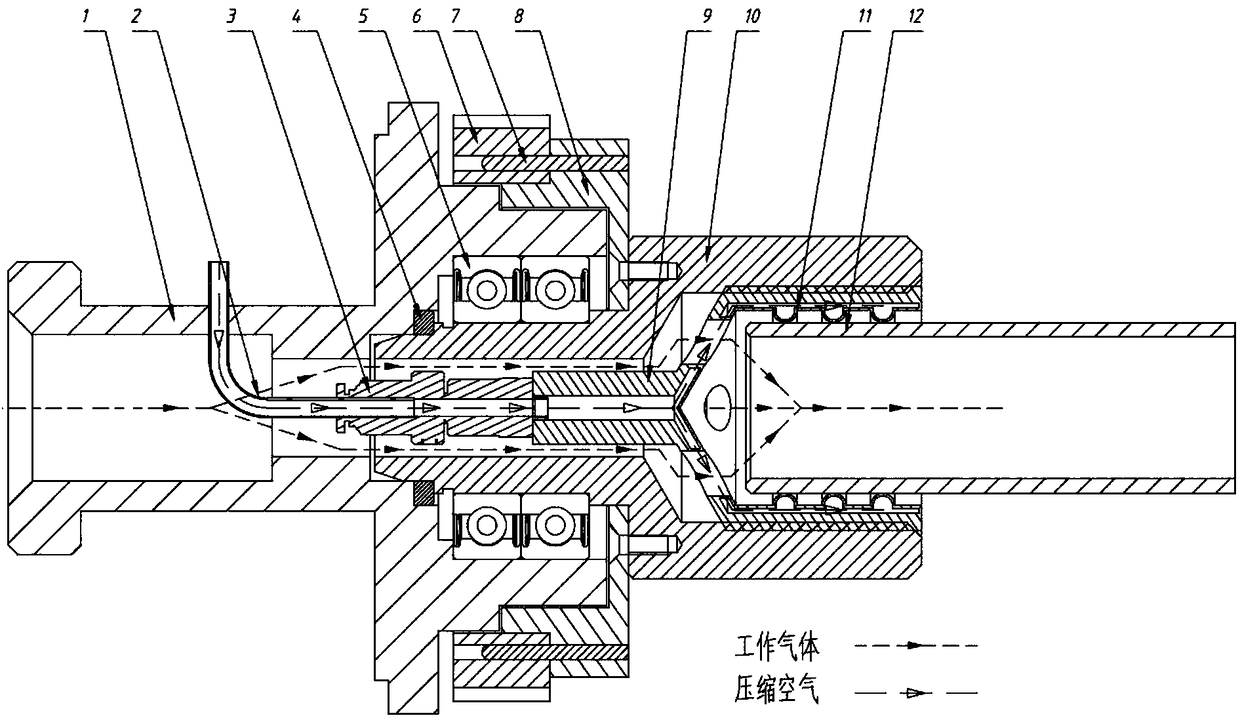
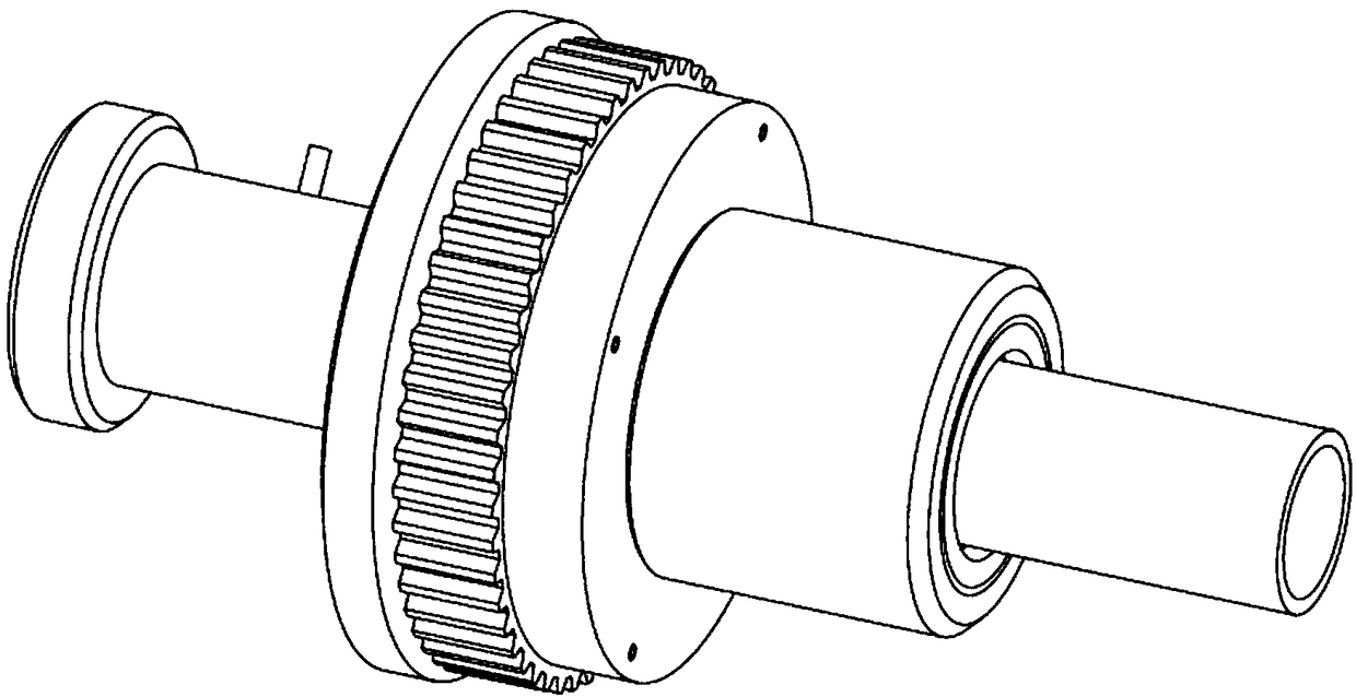
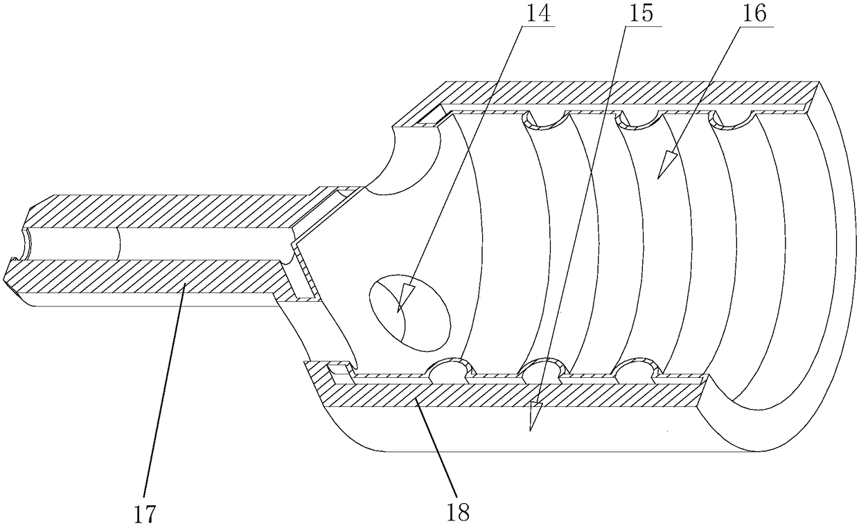
[0029] refer to Figure 1 to Figure 3 , in this preferred embodiment, an automatic clamping device for a l...


PUM


Abstract

The invention discloses an automatic clamping device for a liner tube in PCVD equipment. The automatic clamping device comprises a fixed end and a rotatable end, wherein the fixed end comprises a fixed supporting shaft sleeve and an air tube; the rotatable end comprises a rotatable sealing clamping sleeve, a rotatable shaft sleeve, a synchronous pulley and a connecting flange; the rotatable sealing clamping sleeve comprises a body and an inner rubber layer located in the body, an interlayer between the inner rubber layer and the body is hollow and is communicated with the air tube, a hollow protruding heatproof rubber ring is formed in the inner rubber layer, the heatproof rubber ring is expanded when compressed gas is introduced into the air tube, and thus the heatproof rubber ring compactly fits the periphery of the liner tube to clamp the liner tube; an air inlet hole is formed in the body, and is communicated with an inner cavity of the fixed supporting shaft sleeve to allow work gas to enter the liner tube. According to the automatic clamping device for the liner tube in the PCVD equipment, automatic clamping of the liner tube is achieved.

Description

technical field [0001] The invention relates to the technical field of production and preparation of optical fiber preform rods, in particular to an automatic clamping device for liner tubes in PCVD equipment. Background technique [0002] During the preform preparation process using PCVD (Plasma activated Chemical Vapor Deposition, plasma activated chemical vapor deposition method), the deposition of high-purity core rods is the key to high-quality preform rods. At present, the clamping of the liner used for the deposition mandrel mostly adopts the form of mechanical nuts and O-rings to solve the problem of clamping and sealing of the liner. However, the existing methods have the following deficiencies: [0003] 1. There are many types of liners, and liners with different specifications and outer diameters need to be matched with O-rings and lock nuts of different specifications; [0004] 2. The sealing performance of a single O-ring is poor, and there is a risk of workin...

Claims


Application Information

Patent Timeline
Patent Type & Authority Applications(China)
IPC IPC(8): C03B37/018
CPCC03B37/01892
Inventor 武启吴骏王珂邓睿何勤国朱继红张欣
Owner YANGTZE OPTICAL FIBRE & CABLE CO LTD
Learn More